


3: Installation: EDS4100
EDS Device Servers User Guide 23
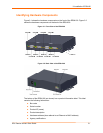
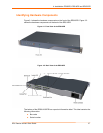
Ethernet Port
The back panel of the EDS4100 provides an RJ45 Ethernet port. This port can connect to
an Ethernet (10 Mbps) or Fast Ethernet (100 Mbps) network. The Speed LED on the
back of the EDS4100 shows the connection of the attached Ethernet network. The
EDS4100 can be configured to operate at a fixed Ethernet speed and duplex mode (half-
or full-duplex) or auto-negotiate the connection to the Ethernet network.
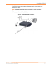
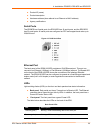
Terminal Block Connector
The back of the EDS4100 has a terminal block screw connector for attaching to an
appropriate power source, such as those used in automation and manufacturing
industries. The terminal block connector supports a power range from 42 VDC to
56 VDC. It can be used with the EDS4100’s barrel power connector and PoE capabilities
as a redundant power source to the unit.
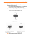
Figure 3-5. Terminal Block Connector Pin Assignments
Pin Signal
Top V+
Middle V-
Bottom Ground
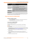
LEDs
Light-emitting diodes (LEDs) on the front and back panels show status information.
Back panel. Each serial port has a Transmit and a Receive LED. The Ethernet
connector has Speed and Activity LEDs. In addition, the back panel has a Power
LED and a Status LED.
Front panel. The front panel has a green Power LED.
The table below describes the LEDs on the back of the EDS4100.
Figure 3-6 .Back Panel LEDs
LED Description
Transmit (green) Blinking = EDS is transmitting data on the serial port.
Receive (yellow) Blinking = EDS is receiving data on the serial port.
Power (green) On = EDS is receiving power.
Status (yellow) Fast blink = initial startup (loading OS).
Slow blink (once per second) = operating system startup.
On = unit has finished booting.
On = EDS is connected to a 100 Mbps Fast Ethernet network. Speed (yellow)
Off = EDS is connected to a 10 Mbps Ethernet network.
Activity (green) Blink = EDS is sending data to or receiving data from the Ethernet
network.