64
Lenovo G560 Hardware Maintenance Manual
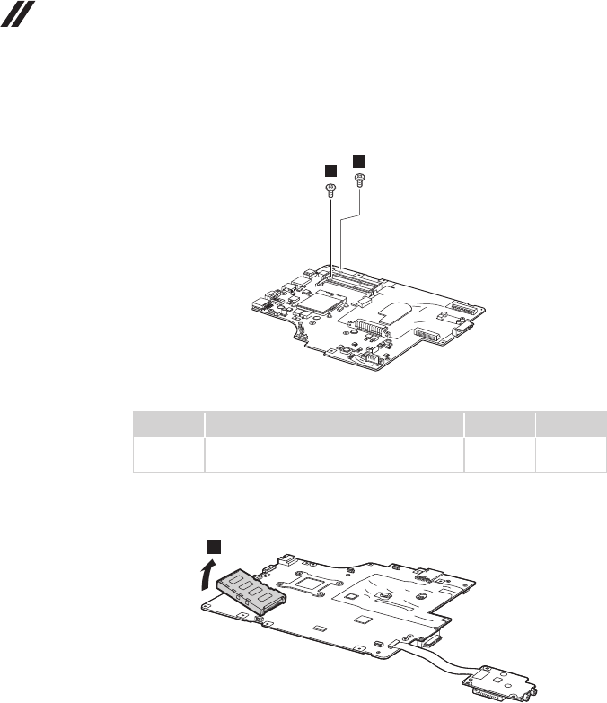
Figure 13. Removal steps of system board and ExpressCard slot assembly
(continued)
Turn the system board over and remove two screws
5
.
4
4
Step Screw (quantity) Color Torque
5
M2.0 × 3 mm, fl at-head, nylon-coated (2) Black 0.25 Nm
(2.5 kgfcm)
Remove the ExpressCard slot assembly in the direction shown by arrow
6
.
6


