


2. Connect any required cables to the adapter (see “Internal cable routing and
connectors” on page 163.)
Attention:
v When you route cables, do not block any connectors or the ventilated space
around any of the fans.
v Make sure that cables are not routed on top of components under the PCI
riser-card assembly.
v Make sure that cables are not pinched by the server components.
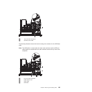
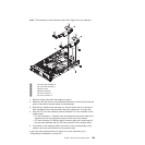
3. Align the PCI riser-card assembly with the selected PCI connector on the
system board:
v PCI-riser connector 1: Carefully fit the two alignment slots on the side of the
assembly onto the two alignment brackets on the side of the chassis; align
the rear of the assembly with the guides on the rear of the server.
v PCI-riser connector 2: Carefully align the bottom edge (the contact edge) of
the riser-card assembly with the riser-card connector on the system board;
align the rear of the assembly with the guides on the rear of the server.
4. Press down on the assembly. Make sure that the riser-card assembly is fully
seated in the riser-card connector on the system board.
5. Perform any configuration tasks that are required for the adapter.
6. Install the server cover (see “Completing the installation” on page 227).
7. Slide the server into the rack.
8. Reconnect the external cables; then, reconnect the power cords and turn on the
peripheral devices and the server.
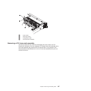
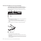
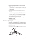
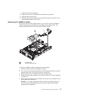
Removing an Ethernet adapter
To remove an Ethernet adapter, complete the following steps:
1. Read the safety information that begins on page 3 and “Installation guidelines”
on page 11.
2. Turn off the server and peripheral devices and disconnect all power cords and
external cables.
3. Remove the cover.
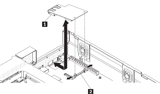
4. Remove the PCI riser card 1.
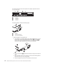
5. Push the tabs on the adapter bracket 2 outwards, then lift the front end of the
adapter 1 to disconnect it from the system board. Then lift it out of the server.
6. Install the cover.
Chapter 6. Removing and installing FRUs 173