


• “1170 LCD unit” on page 86
• “2010 LCD bezel assembly” on page 96
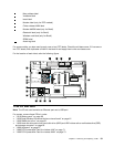
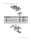
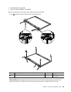
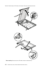
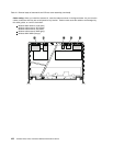
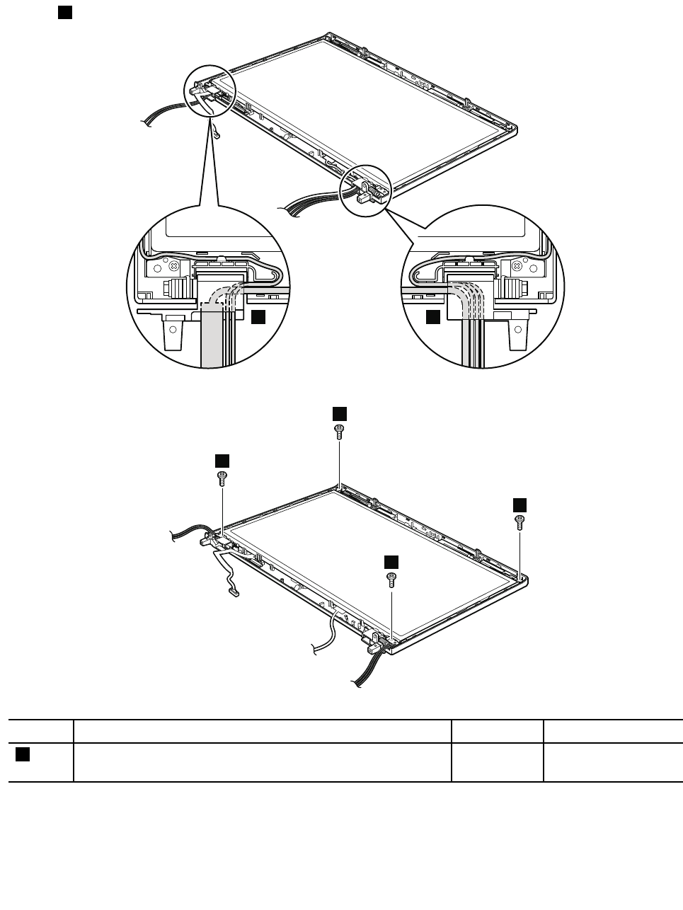
Table 40. Removal steps of LCD cable, camera cable, LCD panel, and hinges
In step 1 , release the antenna cables from the left and right hinges.
1 1
2
2
2
2
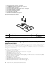
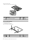
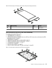
Step Screw (quantity) Color
Torque
2
M2.5 × 6 mm, wafer-head, nylon-coated (4)
Black 0.392 Nm
(4.0 kgfcm)
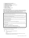
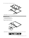
When installing: When attaching the LCD panel to the cover, press the left and right edges covered with metal
gently with your ngers. DO NOT press the surface of the panel or apply any excessive force to the panel.
Chapter 9. Removing and replacing a FRU 99