


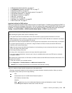
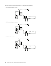
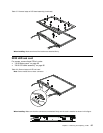
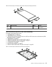
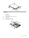

Table 40. Removal steps of LCD cable, camera cable, LCD panel, and hinges (continued)
9
9
9
9
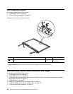
10
10
Step Screw (quantity) Color
Torque
9
M2 × 3 mm, wafer-head, nylon-coated (4) Silver
0.181 Nm
(1.85 kgfcm)
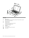
2050 Antenna kit and LCD rear cover assembly
For access, remove these FRUs in order:
• “1010 Battery pack” on page 60
• “1030 DIMM slot cover” on page 62
• “1050 Hard disk drive slot cover, hard disk drive (HDD) and HDD rubber rails or solid state drive (SSD)
and storage converter” on page 65
• “1060 Keyboard” on page 67
• “1080 PCI Express Mini Card for wireless LAN” on page 71
• “1090 PCI Express Mini Card for wireless WAN” on page 73
• “1100 Keyboard bezel assembly” on page 75
• “1170 LCD unit” on page 86
• “2010 LCD bezel assembly” on page 96
• “2040 LCD cable, camera cable, LCD panel, and hinges” on page 98
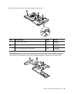
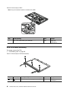
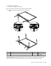
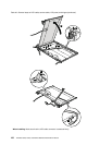
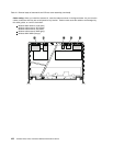
Table 41. Removal steps of antenna kit and LCD rear cover assembly
2
2
2
2
3
3
3
3
1
1
Chapter 9. Removing and replacing a FRU 101