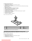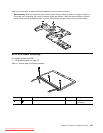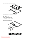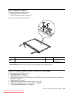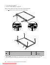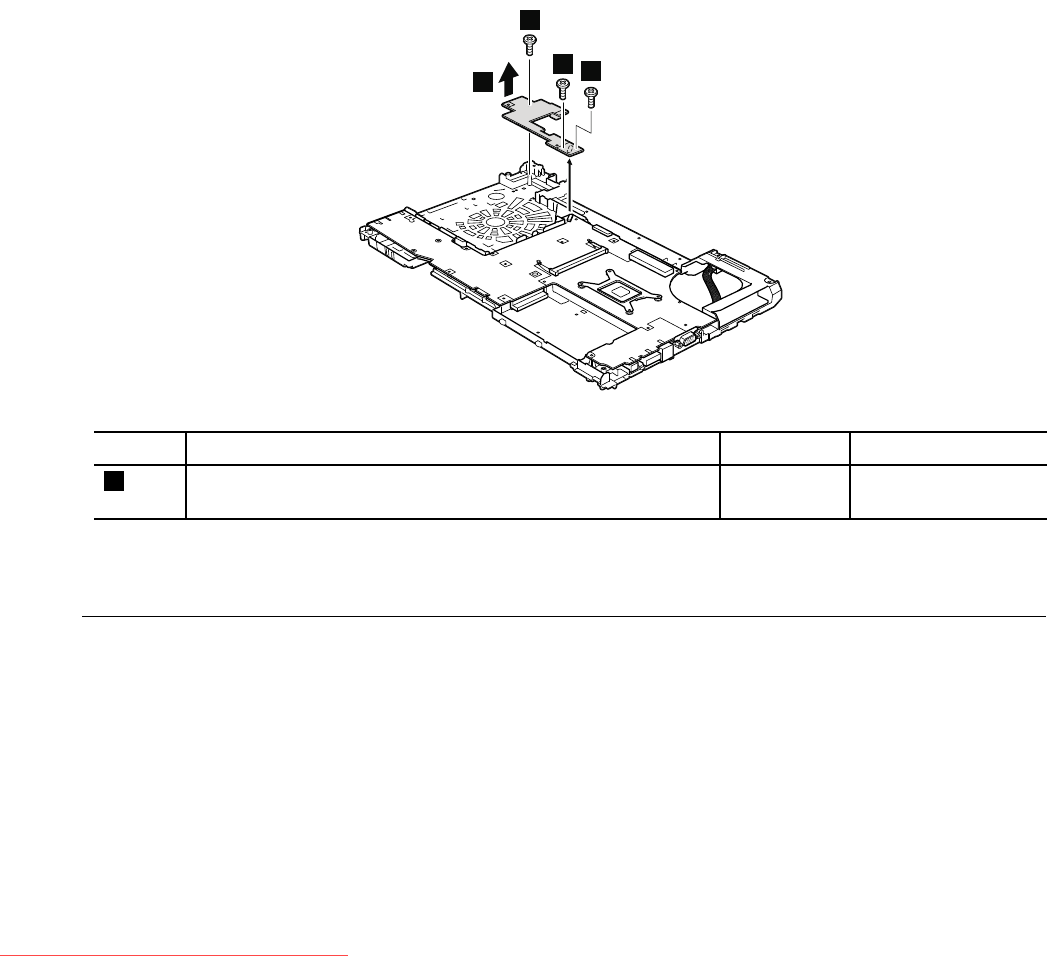
For access, remove these FRUs in order:
• “1010 Battery pack” on page 70
• “1020 Serial Ultrabay Enhanced device or travel bezel” on page 71
• “1030 DIMM slot cover” on page 73
• “1050 Hard disk drive slot cover, hard disk drive and HDD rubber rails or solid state drive and storage
converter” on page 74
• “1060 Keyboard” on page 76
• “1080 PCI Express Mini Card for wireless LAN” on page 80
• “1090 PCI Express Mini Card for wireless WAN” on page 82
• “1100 Keyboard bezel assembly” on page 84
• “1110 Bluetooth daughter card (BDC-2.1)” on page 87
• “1120 Backup battery” on page 88
• “1130 Smart Card or Contactless Smart Card or Smart Card dummy spacer” on page 89
• “1140 Speaker assembly” on page 92
• “1150 Thermal module” on page 94
• “1170 LCD unit” on page 97
• “1180 Base cover assembly” on page 100
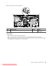
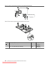
Table 34. Removal steps of I/O sub card
2
1
1
1
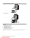
Step Screw (quantity) Color
Torque
1
M2 × 7 mm, at-head, nylon-coated (3) Silver
0.181 Nm
(1.85 kgfcm)
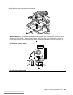
When installing: Make sure that the connector is attached rmly.
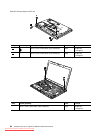
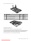
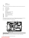
1200 System board assembly and magnesium structure frame
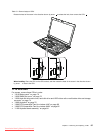
Note: The system board does not contain neither the Ethernet port nor the modem port. See “1190 I/O
sub card” on page 102 for these ports.
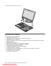
For access, remove these FRUs in order:
• “1010 Battery pack” on page 70
• “1020 Serial Ultrabay Enhanced device or travel bezel” on page 71
• “1030 DIMM slot cover” on page 73
• “1040 DIMM (bottom slot)” on page 73
Chapter 9. Removing and replacing a FRU 103
Downloaded from LpManual.com Manuals


