


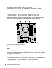
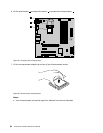
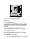
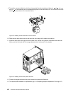

Figure 32. Removing the eight screws that secure the system board
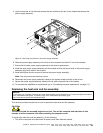
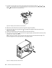
9. Carefully slide the system board so that it can be released from the mounting studs that secure the
system board in place.
10. Lift the system board out of the chassis.
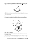
11. Remove the microprocessor from the failing system board and install it on the new system board.
See “Replacing the microprocessor” on page 97
.
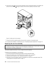
12. Install the new system board into the chassis by aligning the eight mounting studs in the chassis with the
corresponding holes in the new system board. Carefully slide the new system board into the chassis until
it is secured in place by the mounting studs. Then, install the eight screws to secure the system board.
13. Install all memory modules and PCI cards removed from the failing system board on the new system
board. See “Installing or replacing a memory module” on page 84 and “Installing or replacing a PCI
card” on page 81
.
14. Install the heat sink and fan assembly and connect the heat sink and fan assembly cable to the new
system board. See “Replacing the heat sink and fan assembly” on page 95
.
15. Reconnect all remaining cables to the system board. See “Locating parts on the system board”
on page 77.
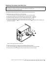
16. Install the hard disk drive. See “Replacing the primary hard disk drive” on page 103 and See “Replacing
the secondary hard disk drive” on page 105.
17. To complete the replacement, go to “Completing the parts replacement” on page 113.
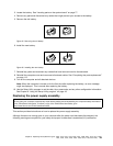
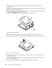
The failing system board must be returned with a microprocessor socket cover to protect the pins during
shipping and handling.
To install the microprocessor socket cover, do the following:
Chapter 8. Replacing FRUs (Machine Types: 4468, 4473, 4476, 4479, 4495, 4497, 4499, 4504, 4513, 4517, 4524,
7021, 7032, 7034, 7049, 7052, 7053, 7073, 7136, and 7178.) 101