


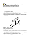
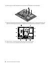
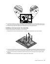
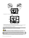
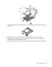

6. Firmly press the memory module 1 straight down into the slot by applying pressure on both ends of
the memory module simultaneously. The retaining clips 2 snap into the locked position when the
memory module is rmly seated in the slot.
Note: If there is a gap between the memory module and the retaining clips, the memory module has not
been correctly inserted. Open the retaining clips, remove the memory module, and then reinsert it.
7. Go to “Completing the FRU installation” on page 109.
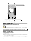
Replacing the microprocessor fan assembly
Attention:
Do not open your computer or attempt any repair before reading and understanding the “Important Safety
Information” on page 1.
This section provides instructions on how to replace the microprocessor fan assembly.
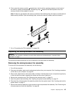
Removing the microprocessor fan assembly
To remove the microprocessor fan assembly, do the following:
1. Turn off the computer.
2. Disconnect all cables, power cords, and external options from your computer. See “Locating connectors
on the rear of your computer” on page 68.
3. Place a soft, clean towel or cloth on the desk or surface. Hold the sides of your computer and gently lay
it down so that the screen is against the surface and the cover is facing up.
4. Remove the computer cover. See “Removing the computer cover” on page 74.
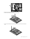
5. Open the system board shielding. See “Opening the system board shielding” on page 75.
6. Disconnect the microprocessor fan assembly cables from the system board. See “Locating parts on the
system board” on page 71.
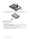
7. Remove the heat sink assembly to gain access to the microprocessor fan assembly. See “Removing the
microprocessor and heat sink assembly” on page 89.
Chapter 9. Replacing FRUs 85