


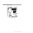
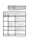

Table 4. System-board LEDs (continued)
LED Description
Baseboard management
controller heartbeat LED
This LED flashes to indicate that the IMM is functioning
normally.
Standby power LED When this LED is lit, it indicates that the server is connected
to ac power.
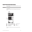
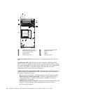
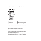
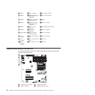
The following table describes the LEDs on the system board and extender card and
suggested actions to correct the detected problems.
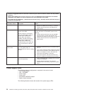
v Follow the suggested actions in the order in which they are listed in the Action column until the problem
is solved.
v See the parts listing in the Hardware Maintenance Manual to determine which components are customer
replaceable units (CRUs) and which components are field replaceable units (FRUs).
v If an action step is preceded by “(Trained service technician only),” that step must be performed only by a
trained service technician.
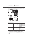
System error or
information LED lit Description Action
DIMM 1 to DIMM 6
error LEDs
A DIMM has failed or is incorrectly
installed.
1. Remove the DIMM that is indicated by a lit error
LED.
2. Reseat the DIMM.
3. Replace the following components one at a time,
in the order shown, restarting the server each time:
a. DIMM
b. (Trained service technician only) System board
CPU 1 error LED Microprocessor 1 has failed, is
missing, or has been incorrectly
installed.
Note: (Trained service technician
only) Make sure that the
microprocessors are installed in the
correct sequence; see the
procedures for removing and
installing a microprocessor in the
Hardware Maintenance Manual.
1. Check the system-event log to determine the
reason for the lit LED.
2. (Trained service technician) Reseat the failing
microprocessor.
3. Replace the following components one at a time,
in the order shown, restarting the server each time:
a. (Trained service technician only) Failing
microprocessor
b. (Trained service technician only) System board
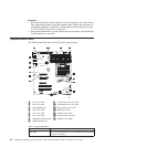
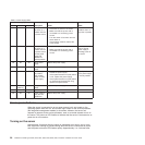
CPU mismatch LED A mismatched microprocessor has
been installed.
Note: All microprocessors must
have the same speed and cache
size.
1. Run the Setup Utility and view the microprocessor
information to compare the installed
microprocessor specifications.
2. (Trained service technician only) Remove and
replace one of the microprocessors so that they
both match.
VRM failure LED Microprocessor 2 VRM has failed or
is incorrectly installed.
1. Reseat the VRM
2. Replace the following components one at a time,
in the order shown, restarting the server each time:
a. VRM
b. (Trained service technician only) System board
3. Replace the VRM
System-board error
LED
System-board CPU VRD, power
voltage regulators, or both have
failed.
(Trained service technician only) Replace the system
board.
Chapter 4. Server controls, LEDs, and power 23