


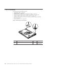
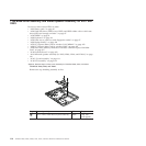
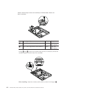
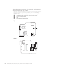
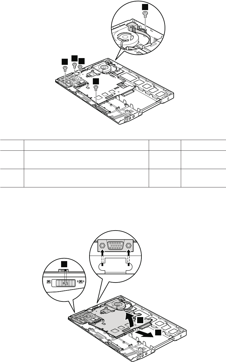
Table 23. Removal steps of base cover assembly for ThinkPad X200s, X200si, and
X201s (continued)
4
5
4
4
4
Step Screw (quantity) Color Torque
4 M2 × 3.5 mm, wafer-head, nylon-coated (4) Silver 0.181 Nm
(1.85 kgfcm)
5 M2 × 3 mm, large-head, nylon-coated (1) Silver 0.181 Nm
(1.85 kgfcm)
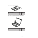
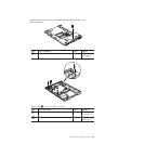
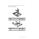
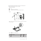
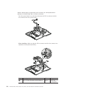
In step 6 and 7, remove the system board, the DC-in connector, and the fan
assembly together from the base cover assembly.
6
7
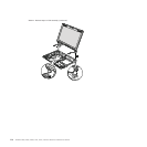
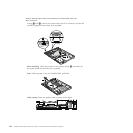
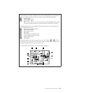
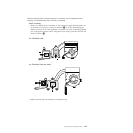
a
When installing: Attach the wireless radio switch as shown in the figure a.
122 ThinkPad X200, X200s, X200si, X201, X201i, and X201s Hardware Maintenance Manual