


General information 1-35
5023-110
Control system structure
Electrical system and function
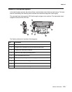
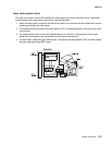
The engine board controls most of the main electrical parts in this printer.
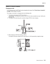
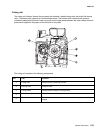
Control of print process
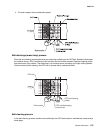
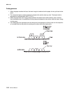
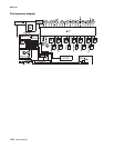
Control block diagram
Note: A micro CPU mounted on the engine board controls the print processes.
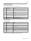
No. Control process Function
1 Print process control Controls print process from paper feed through paper exit.
2 Laser output control Automatically controls laser output to the default.
3 Fuser temperature control Controls fuser heater, allowing heated roller to reach default
temperature.
4 Toner sensing control Controls sensing of toner empty status.
5 Interface control (video signal) Processes the input and output signal with external controller
computer.
6 Operator panel indicator Displays printer operation status.
7 Error control Controls safe stop procedures when errors occur.
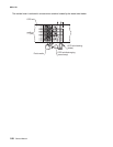
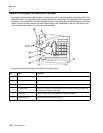
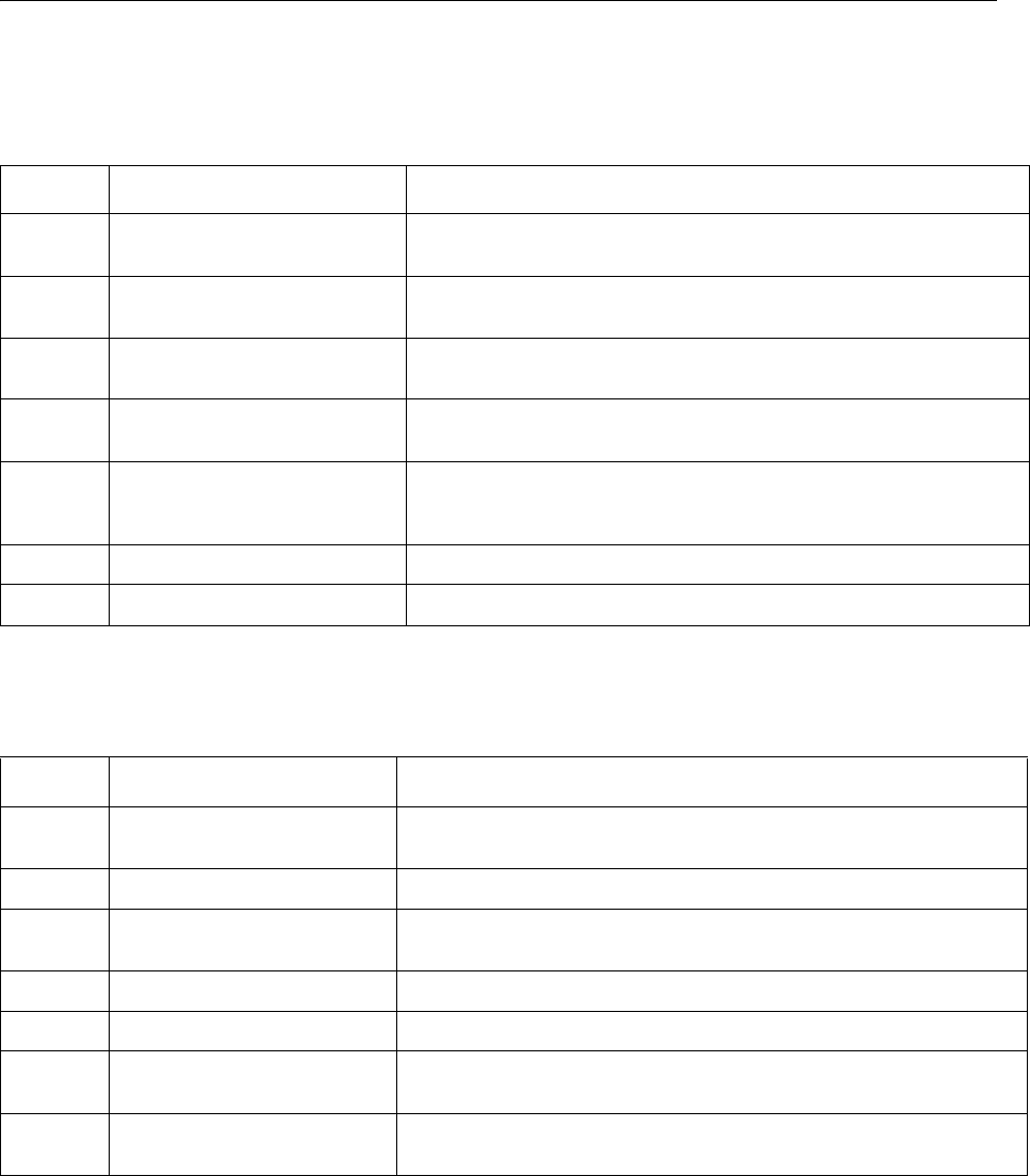
No. Control process Function
1 Sequence control Controls print sequence of printer.
2 Temperature control Controls temperature of fuser unit.
3 Consumables’ life control Controls toner empty status for each toner cartridge and life of periodic
replacement parts.
4 Operator panel control Controls operator panel indication and operator signals.
5 Error processing control Senses errors occurring as well as stop procedures.
6 Interface control Controls receipt and transmission of interface signals from external
controller.
7 Laser control Controls laser scanning and laser power.