


11
206-4157
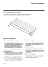
Typical System Installation
(see also Typical Setup Flow Charts and VPN Network Connections Overview diagrams)
1. If your system is using ASI output, make the following two connections; otherwise, go to
step 2.
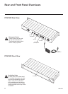
• Connect a 75 ohm BNC-to-BNC coaxial cable between ASI OUT on the PCS150R and
ASI IN on the modulator.
Note: The BNC cable must be less than 30 feet (9.2 meters) in length.
• Connect an RF coaxial cable between IF OUT on the modulator and IF IN on the upcon-
verter.
2. Connect one end of a CAT5 RJ-45 Ethernet cable to the ETHERNET-0 port on the PCS150R
rear panel, and connect the other end of the cable to the institution’s network.
3. Connect the PCS150R power supply to the POWER connector on the PCS150R rear panel.
4. Use the straight-through serial cable and, if necessary, the USB adapter to connect a PC to
the RS-232 port on the PCS150R rear panel. (This step will enable you to verify the network
connection once power is applied in step 6.)
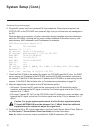
5. Using HyperTerminal or an equivalent terminal emulation program on the PC, congure the
serial port as follows: Bits per second = 115200; Data bits = 8; Parity = None; Stop bits = 1;
Flow Control = None
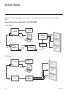
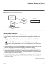
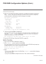
System Setup (Cont.)
Laptop
PC
Pro:Centric
VPN Server
Internet/
VPN
VPN Client
VPN Client
PCS150R
VPN Network Connections Overview
(Continued on next page)