


Operation 35
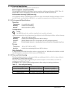
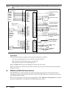
4.4 Rectifiers
The rectifiers provide isolated, filtered and regulated DC power, from either a single-phase AC
source (Helios Rectifier 100/48) or a three-phase AC source (Helios Rectifier 200I/48 or 200E/48),
for charging a positive grounded battery.
The nominal output is adjustable over the range of -46 to -59.5 V to float a 23 or 24 cell battery
string.
The rectifiers are equipped with AC input and DC output circuit breakers, a digital ammeter,
potentiometers for the adjustment of thresholds, and LED indicators for alarm indications.
The rectifiers use high frequency switching technology and forced air-cooling.
Refer to the appropriate rectifier user manual listed in
6.0 - Reference Documents
for detailed
operation information on the Helios Rectifier 100/48, the Helios Rectifier 200I/48, or the Helios
Rectifier 200E/48.
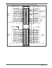
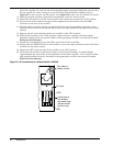
4.5 AC Junction Box
The AC junction box is part of the rectifier cabinet used for the Helios Rectifier 200E/48. It is
located at the top of the cabinet for top fed systems, or at the bottom of the cabinet for bottom fed
systems.
The AC junction box provides AC connection interface for up to six rectifiers and facilitates the
addition and/or replacement of rectifiers in a working system. The AC supply from the AC service
panel is hard wired inside the box at the time of the initial installation. Detailed cabling and con-
necting guidelines for the AC junction box can be found in
5.0 - Maintenance.
The rectifiers are provided with a factory-installed AC cord equipped with a male connector. This
male connector is plugged into a matching female receptacle at the rear of the AC junction box.
For the complete procedures for adding or replacing a rectifier, refer to
5.0 - Maintenance.
Note
that caps are provided to protect the unused female receptacles.
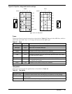
4.6 Distribution Panels
All distribution panels provide local alarm indication on the panel itself, and alarm extension to
the controller for additional indication on the controller and the cabinet and further extension to
remote alarm facilities.
4.7 Terminating Assemblies (Optional)
Terminating assemblies are optional devices used to facilitate the connecting of loads to distribu-
tion fuses or circuit breakers larger than 199 A. These assemblies can be used in top fed systems
only (they cannot be used on bottom fed systems). Each terminating assembly provides connection
facilities for up to six loads without having to route the cables inside the cabinet during installa-
tion.
Two terminating assemblies can be used on an auxiliary distribution cabinet, while only one ter-
minating assembly can be used on a main control and distribution cabinet.
!
WARNING
PREVENTING ELECTRICAL SHOCKS
WHEN OPENING THE DOOR OR WIRING THE AC INPUT OF
THE RECTIFIERS INSIDE THE JUNCTION BOX, ENSURE THAT
THE ASSOCIATED AC BREAKERS, LOCATED IN THE AC
SERVICE PANEL, ARE IN THE OFF POSITION AND THAT A
WARNING TAG CLEARLY INDICATES THAT THESE BREAKERS
ARE TO REMAIN OFF UNTIL THE AC WIRING HAS BEEN
COMPLETED. DO NOT INSERT FUSES, OR OPERATE CIRCUIT
BREAKER OR SWITCHES TO ON UNTIL THE WIRING IS
COMPLETED AND YOU ARE INSTRUCTED TO DO SO.