


iv
TABLES
Table 1 Rectifier cabinets. . . . . . . . . . . . . . . . . . . . . . . . . . . . . . . . . . . . . . . . . . . . . . . . . . . . . . . . . . . . . . 5
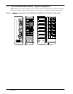
Table 2 Control and distribution cabinets . . . . . . . . . . . . . . . . . . . . . . . . . . . . . . . . . . . . . . . . . . . . . . . . 5
Table 3 Auxiliary distribution cabinets . . . . . . . . . . . . . . . . . . . . . . . . . . . . . . . . . . . . . . . . . . . . . . . . . . 5
Table 4 Mechanical specifications of the cabinet (empty) . . . . . . . . . . . . . . . . . . . . . . . . . . . . . . . . . . . . 6
Table 5 Mechanical specifications of the Conventional Controller . . . . . . . . . . . . . . . . . . . . . . . . . . . . . 7
Table 6 Mechanical specifications of the fuse panels. . . . . . . . . . . . . . . . . . . . . . . . . . . . . . . . . . . . . . . . 8
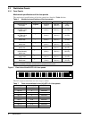
Table 7 Fuse sizes available for the (20) QFF 0-5 A fuse panels. . . . . . . . . . . . . . . . . . . . . . . . . . . . . . . 8
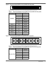
Table 8 Fuse sizes available for the (16) QFF 0-5 A & (12) ABS 5-30 A fuse panels . . . . . . . . . . . . . . . 9
Table 9 Fuse sizes available for the (16) QFF 0-5 A & (6) TPN 5-30 A fuse panels . . . . . . . . . . . . . . . . 9
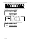
Table 10 Fuse sizes available for the (8) TPN 5-30 A fuse panels. . . . . . . . . . . . . . . . . . . . . . . . . . . . . . 10
Table 11 Fuse sizes available for the (4) RS100P 70-100 A fuse panels . . . . . . . . . . . . . . . . . . . . . . . . . 10
Table 12 Fuse sizes available for the (4) CRS200P 150-200 A/
(4) CRS200P 150-200 A (w/load shunts) fuse panels . . . . . . . . . . . . . . . . . . . . . . . . . . . . . . . . 11
Table 13 Fuse sizes available for the (4) TPL 225-600 A fuse panels . . . . . . . . . . . . . . . . . . . . . . . . . . . 11
Table 14 Fuse sizes available for the (18) TPS 1-70 A fuse panel . . . . . . . . . . . . . . . . . . . . . . . . . . . . . . 12
Table 15 Electrical specifications of the fuse panels . . . . . . . . . . . . . . . . . . . . . . . . . . . . . . . . . . . . . . . . 13
Table 16 Mechanical specifications of the circuit breaker panels . . . . . . . . . . . . . . . . . . . . . . . . . . . . . . 13
Table 17 Plug-in circuit breakers available for the (24) Plug-In 1-100 A circuit breaker panel . . . . . . 14
Table 18 Circuit breaker sizes available for the (4) 70-250 A circuit breaker panel . . . . . . . . . . . . . . . 15
Table 19 Circuit breaker kits available for the (2) 400 A circuit breaker panel. . . . . . . . . . . . . . . . . . . 16
Table 20 Circuit breaker kits available for the (1) 600-700 A circuit breaker panel . . . . . . . . . . . . . . . 16
Table 21 Electrical specifications of the circuit breaker panels . . . . . . . . . . . . . . . . . . . . . . . . . . . . . . . 17
Table 22 Mechanical specifications of a single lamination . . . . . . . . . . . . . . . . . . . . . . . . . . . . . . . . . . . 18
Table 23 Mechanical specifications of the MPS300 and MPA100 power shelves. . . . . . . . . . . . . . . . . . 20
Table 24 Mechanical specifications of the Helios Rectifier 100/48 . . . . . . . . . . . . . . . . . . . . . . . . . . . . . 21
Table 25 Electrical specifications of the Helios Rectifier 100/48. . . . . . . . . . . . . . . . . . . . . . . . . . . . . . . 22
Table 26 Mechanical specifications of the Helios Rectifiers 200I/48 and 200E/48. . . . . . . . . . . . . . . . . 22
Table 27 Electrical specifications of the Helios Rectifiers 200I/48 and 200E/48 . . . . . . . . . . . . . . . . . . 24
Table 28 Mechanical specifications of the Helios Monitor 3000/48. . . . . . . . . . . . . . . . . . . . . . . . . . . . . 25
Table 29 Mechanical specifications of the AC junction box . . . . . . . . . . . . . . . . . . . . . . . . . . . . . . . . . . . 26
Table 30 Mechanical specifications of fully equipped power cabinets. . . . . . . . . . . . . . . . . . . . . . . . . . . 26
Table 31 Floor and point loading. . . . . . . . . . . . . . . . . . . . . . . . . . . . . . . . . . . . . . . . . . . . . . . . . . . . . . . . 27
Table 32 Visual indicators . . . . . . . . . . . . . . . . . . . . . . . . . . . . . . . . . . . . . . . . . . . . . . . . . . . . . . . . . . . . . 28
Table 33 Transmitted alarms . . . . . . . . . . . . . . . . . . . . . . . . . . . . . . . . . . . . . . . . . . . . . . . . . . . . . . . . . . 29
Table 34 Potentiometers . . . . . . . . . . . . . . . . . . . . . . . . . . . . . . . . . . . . . . . . . . . . . . . . . . . . . . . . . . . . . . 29
Table 35 Switches. . . . . . . . . . . . . . . . . . . . . . . . . . . . . . . . . . . . . . . . . . . . . . . . . . . . . . . . . . . . . . . . . . . . 30
Table 36 DIP switch modules . . . . . . . . . . . . . . . . . . . . . . . . . . . . . . . . . . . . . . . . . . . . . . . . . . . . . . . . . . 30
Table 37 Fuse . . . . . . . . . . . . . . . . . . . . . . . . . . . . . . . . . . . . . . . . . . . . . . . . . . . . . . . . . . . . . . . . . . . . . . . 31
Table 38 Test points . . . . . . . . . . . . . . . . . . . . . . . . . . . . . . . . . . . . . . . . . . . . . . . . . . . . . . . . . . . . . . . . . . 31
Table 39 Fault diagnosis . . . . . . . . . . . . . . . . . . . . . . . . . . . . . . . . . . . . . . . . . . . . . . . . . . . . . . . . . . . . . . 39