


iii
FIGURES
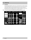
Figure 1 Front view of a typical bottom fed 4000 A Helios DC System 4000/48 power system . . . . . . . 2
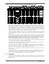
Figure 2 Front view of a typical 6000 A Helios DC System 4000/48 power system . . . . . . . . . . . . . . . . 3
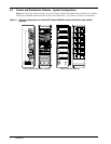
Figure 3 Typical configurations for Helios DC System 4000/48 control, distribution and
rectifier cabinets . . . . . . . . . . . . . . . . . . . . . . . . . . . . . . . . . . . . . . . . . . . . . . . . . . . . . . . . . . . . . . 4
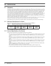
Figure 4 Front view of the Conventional Controller . . . . . . . . . . . . . . . . . . . . . . . . . . . . . . . . . . . . . . . . . 7
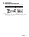
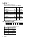
Figure 5 Front view of the 20 QFF 0-5 A fuse panels . . . . . . . . . . . . . . . . . . . . . . . . . . . . . . . . . . . . . . . . 8
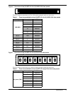
Figure 6 Front view of the (16) QFF 0-5 A & (12) ABS 5-30 A fuse panels . . . . . . . . . . . . . . . . . . . . . . . 9
Figure 7 Front view of the (16) QFF 0-5 A & (6) TPN 5-30 A fuse panels . . . . . . . . . . . . . . . . . . . . . . . . 9
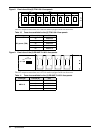
Figure 8 Front view of the (8) TPN 5-30 A fuse panels. . . . . . . . . . . . . . . . . . . . . . . . . . . . . . . . . . . . . . 10
Figure 9 Front view of the (4) RS100P 70-100 A fuse panels . . . . . . . . . . . . . . . . . . . . . . . . . . . . . . . . . 10
Figure 10 Front view of the (4) CRS200P 150-200 A/
(4) CRS200P 150-200 A (w/load shunts) fuse panels . . . . . . . . . . . . . . . . . . . . . . . . . . . . . . . . 11
Figure 11 Front view of the (4) TPL 225-600 A fuse panels . . . . . . . . . . . . . . . . . . . . . . . . . . . . . . . . . . . 11
Figure 12 Front view of the (18) TPS 1-70 A fuse panel . . . . . . . . . . . . . . . . . . . . . . . . . . . . . . . . . . . . . . 12
Figure 13 Front view of the (24) Plug-In 1-100 A circuit breaker panel . . . . . . . . . . . . . . . . . . . . . . . . . 14
Figure 14 Front view of the (4) 70-250 A circuit breaker panel . . . . . . . . . . . . . . . . . . . . . . . . . . . . . . . . 15
Figure 15 Front view of the (2) 400 A circuit breaker panel. . . . . . . . . . . . . . . . . . . . . . . . . . . . . . . . . . . 16
Figure 16 Front view of the (1) 600-700 A circuit breaker panel . . . . . . . . . . . . . . . . . . . . . . . . . . . . . . . 16
Figure 17 Top and side views of the external battery return busbar. . . . . . . . . . . . . . . . . . . . . . . . . . . . 18
Figure 18 Perspective view of the a terminating assemblies . . . . . . . . . . . . . . . . . . . . . . . . . . . . . . . . . . 19
Figure 19 Front view of the MPS300 power shelf (shown empty) . . . . . . . . . . . . . . . . . . . . . . . . . . . . . . 20
Figure 20 Front view of the MPA100 power shelf (shown empty) . . . . . . . . . . . . . . . . . . . . . . . . . . . . . . 21
Figure 21 Front view of the Helios Rectifier 100/48 . . . . . . . . . . . . . . . . . . . . . . . . . . . . . . . . . . . . . . . . . 21
Figure 22 Front view of the Helios Rectifiers 200I/48 and 200E/48. . . . . . . . . . . . . . . . . . . . . . . . . . . . . 23
Figure 23 Front view of the Helios Monitor 3000/48 (without the mounting brackets) . . . . . . . . . . . . . 25
Figure 24 600 A Battery Disconnect Unit . . . . . . . . . . . . . . . . . . . . . . . . . . . . . . . . . . . . . . . . . . . . . . . . . 25
Figure 25 Front view of the AC junction box (with the front panel open) . . . . . . . . . . . . . . . . . . . . . . . . 26
Figure 26 Front view of the Conventional Controller . . . . . . . . . . . . . . . . . . . . . . . . . . . . . . . . . . . . . . . . 28
Figure 27 Shunt range selection settings. . . . . . . . . . . . . . . . . . . . . . . . . . . . . . . . . . . . . . . . . . . . . . . . . . 30
Figure 28 Equalize voltage and duration settings. . . . . . . . . . . . . . . . . . . . . . . . . . . . . . . . . . . . . . . . . . . 31
Figure 29 Terminal blocks and connectors layout at the rear of the Conventional Controller. . . . . . . . 32
Figure 30 Wiring diagram and pin assignment of terminal blocks TB1 to TB4 . . . . . . . . . . . . . . . . . . . 33
Figure 31 Wiring diagram and pin assignment of terminal blocks TB5 and TB6, and
connectors P1 to P26. . . . . . . . . . . . . . . . . . . . . . . . . . . . . . . . . . . . . . . . . . . . . . . . . . . . . . . . . . 34
Figure 32 AC connections in a Helios Rectifier 200E/48. . . . . . . . . . . . . . . . . . . . . . . . . . . . . . . . . . . . . . 42
Figure 33 AC connections in the female receptacle for a Helios Rectifier 200I/48 or
a Helios Rectifier 200E/48 . . . . . . . . . . . . . . . . . . . . . . . . . . . . . . . . . . . . . . . . . . . . . . . . . . . . . 43
Figure 34 AC connections inside the junction box (top fed shown) for a Helios Rectifier 200E/48. . . . . 43
Figure 35 AC cable routing for the Helios Rectifiers 200E/48 in a top fed system . . . . . . . . . . . . . . . . . 44
Figure 36 AC cable routing for the Helios Rectifiers 200E/48 in a bottom fed system . . . . . . . . . . . . . . 44