17
OPERATING INSTRUCTIONS
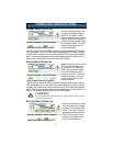
NORMAL MODE OPERATION
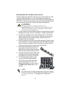
During normal operation, util-
ity power provides energy to
the UPS. The filters, power
factor correction circuit and the
inverter process this power to
provide computer grade power
to connected loads. The UPS
maintains the batteries in a
fully charged state.
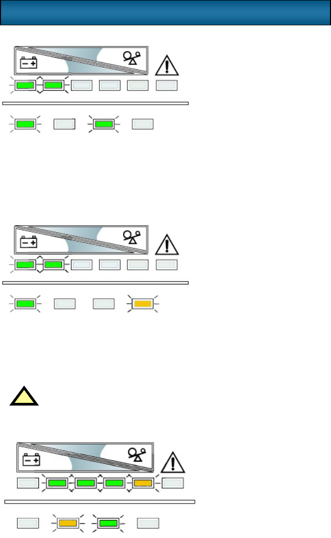
The four green load level LEDs indicate an approximate level of load in
25% increments. If the UPS becomes loaded beyond full rating, the fifth
(amber) LED indicator will illuminate and the UPS will sound an audible
alarm. The display template indicates the percentage of load (26-50% of
load shown in the example above) on the UPS output.
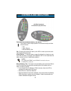
BYPASS MODE OPERATION
Bypass mode occurs when the
OFF button is pressed once
while the UPS is in Normal
Mode. During bypass opera-
tion, utility power provides
energy to the UPS. The utility
power bypasses the inverter
and provides power for the
connected load.
The four green load level LEDs indicate an approximate level of load in
25% increments. If the UPS becomes loaded beyond full rating, the fifth
(amber) LED indicator will illuminate and the UPS will sound an audible
alarm. The display template indicates the percentage of load (26-50% of
load shown in the example above) on the UPS output.
BATTERY MODE OPERATION
Battery mode occurs in event
of an extreme input voltage
condition or complete utility
failure. The battery system
supplies power through the
DC to DC converter to the
inverter to generate power
for the connected load.
!
CAUTION
Turning OFF the UPS while in bypass mode will result in
loss of output power.
Normal Mode Operation at 26-50%
AC INPUT BATTERY UPS ON BYPASS
Bypass Mode Operation at 26-50%
AC INPUT BATTERY UPS ON BYPASS
Battery Mode Operation at 80-61%
AC INPUT BATTERY UPS ON BYPASS


