


i
Table of Contents
1.0 SAFETY PRECAUTIONS ............................................................. 3
2.0 I
NSTALLATION CONSIDERATIONS ..................................................... 4
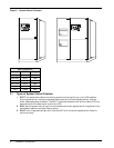
2.1 TypesofSystemControlCabinets ............................................ 6
3.0 U
NLOADING AND HANDLING ........................................................ 7
4.0 I
NSPECTIONS
4.1 ExternalInspections ....................................................... 8
4.2 InternalInspections........................................................ 8
5.0 E
QUIPMENT LOCATION............................................................. 9
6.0 B
ATTERY INSTALLATION
6.1 BatterySafetyPrecautions................................................. 10
6.2 MatchingBatteryCabinets................................................. 13
6.3 Non-StandardBatteries.................................................... 13
7.0 C
ONFIGURING YOUR NEUTRAL AND GROUND CONNECTIONS
7.1 PreferredGroundingConfiguration,Wye-ConnectedService...................... 15
7.2 GroundingConfiguration,DeltaSource....................................... 16
7.3 PreferredGroundingConfigurationwithPower-TieSwitchgear................... 17
7.4 GroundingConfigurations,BatterySystems................................... 18
8.0 W
IRING CONSIDERATIONS
8.1 PowerWiring............................................................ 20
8.2 ControlWiring........................................................... 21
8.3 BatteryWiring........................................................... 22
9.0 W
IRING CONNECTIONS............................................................ 25
10.0 W
IRING INSPECTION
Table1PowerWiringTerminals-FactorySupplied................................... 27
Table2TorqueSpecifications ..................................................... 27
Table 3 Table 310-16 ............................................................ 28
11.0 I
NSTALLATION DRAWINGS ......................................................... 29
12.0 A
PPENDIX A-SITE PLANNING DATA
Table 4 Series 600T Multi-Module Systems, 500-750 kVA - 480 Volt Input. . ............... 81
Table 5 Series 600T Multi-Module Systems, 500-750 kVA - 600 Volt Input . ............... 82
13.0 A
PPENDIX B-FIELD SUPPLIED LUGS
Table6One-HoleLugs .......................................................... 83