


Wiring Inspection 27
10.0 WIRING INSPECTION
1. Verify all power connections are tight.
2. Verify all control wire terminations are tight.
3. Verify all power wires and connections have proper spacing between exposed surfaces, phase-
to-phase and phase-to-ground.
4. Verify that all control wires are run in individual, separate, steel conduit.
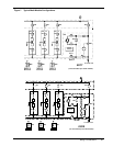
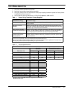
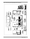
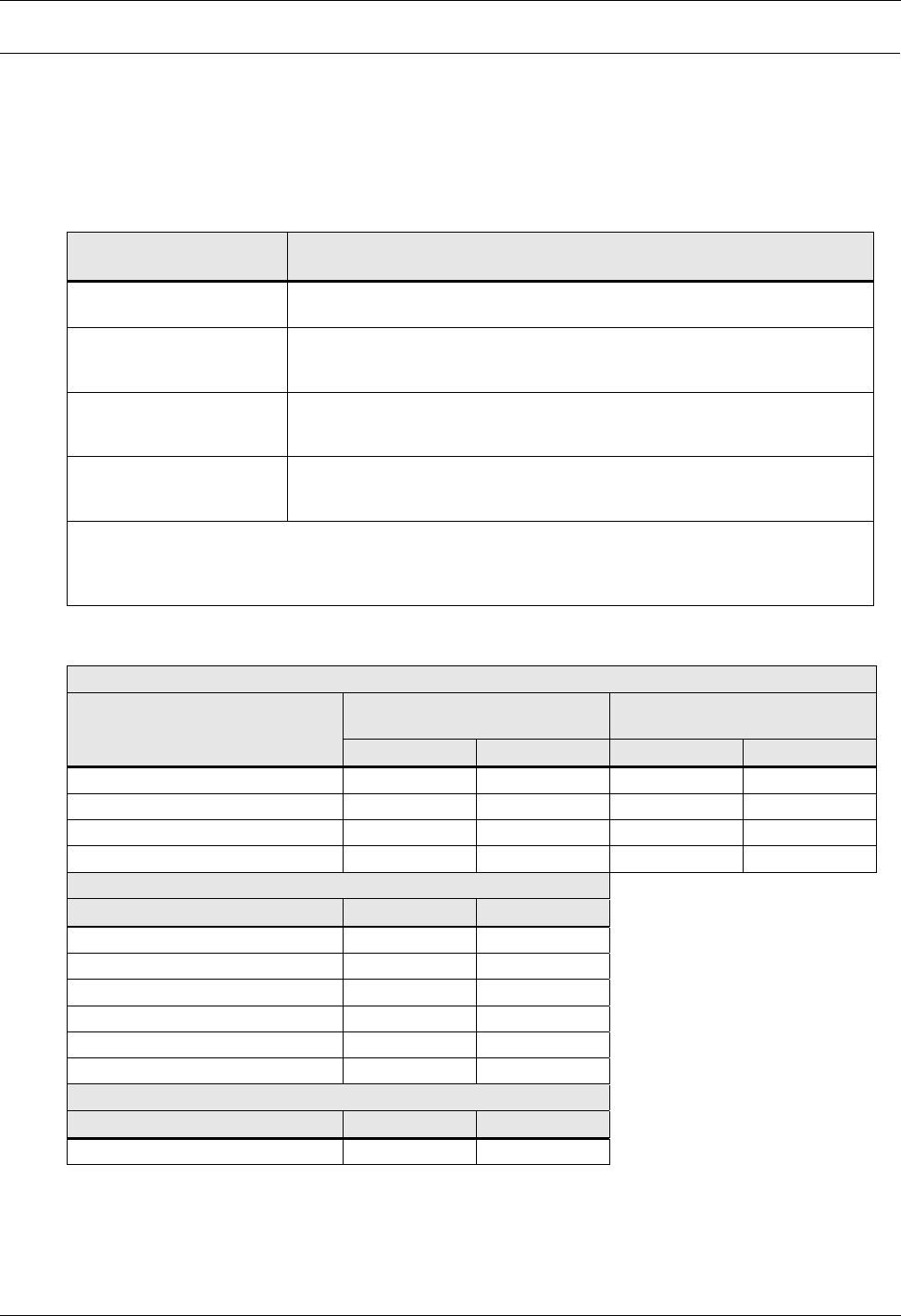
Table 1 Power Wiring Terminals - Factory Supplied
UPS Module Rating Connection Type
500 kVA, 6-Pulse Rectifier All power connections are top or bottom cable entry to busbars on the right
side of module.
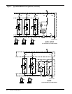
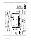
500 kVA, 12-Pulse
Rectifier
Busbars for DC input, AC output, Neutral and Ground are provided on the
right side of module, with top or bottom cable entry. Rectifier input is top entry
directly to lugs on top of input circuit breaker.
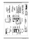
625-750 kVA, standard
models with standard input
Busbars for AC output, Neutral and Ground are provided on the right side of
module, with top or bottom cable entry. Rectifier input is top entry directly to
lugs on top of input circuit breaker. DC input is top entry to bus bars.
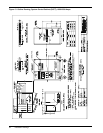
750 kVA/675 kW and other
modules with optional
input busbar kit
Busbars for AC output, Neutral and Ground are provided on the right side of
module, with top or bottom cable entry. Rectifier input and DC input are top
entry to bus bars.
Use 75°C copper wire. Select wire size based on the ampacities in Table 310-16 (see Table 3 of this
manual) and associated notes of the National Electrical Code (NFPA 70).
Use commercially available solderless lugs for the wire size required for your application. Connect wire to
the lug using tool and procedure specified by the lug manufacturer.
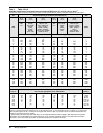
Table 2 Torque Specifications
Nut and Bolt Combinations
Bolt Shaft Size
Grade 2
Standard
Electrical Connections
with Belleville Washers
Lb-in N-m Lb-in N-m
1/4 53 6.0 46 5.2
5/16 107 12 60 6.8
3/8 192 22 95 11
1/2 428 48 256 29
Circuit Breakers With Compression Lugs (For Power Wiring)
CableSizeorRange Lb-in N-m
#6 - #4 100 11
#3 - #1 125 14
1/0 - 2/0 150 17
3/0 - 200 MCM 200 23
250 - 400 MCM 250 28
500 - 700 MCM 300 34
Terminal Block Compression Lugs (For Control Wiring)
AWG Wire Size or Range Lb-in N-m
#22 - #14 3.5 to 5.3 0.4 to 0.6
Use the values in this table unless the equipment is labeled with a
different torque value.