


Control Panel Description
20
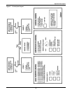
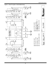
3.0 CONTROL PANEL DESCRIPTION
Refer to Figure 5.
3.1 Mimic Panel
The Mimic panel consists of the following:
• UPS SYSTEM 1 - PRIMARY BYPASS
• UPS SYSTEM 2 - PRlMARY BYPASS
• UPS SYSTEM 1 - ON BYPASS
• UPS SYSTEM 2 - ON BYPASS
• LOAD 1 CIRCUIT BREAKER
• LOAD 2 CIRCUIT BREAKER
• TIE CIRCUIT BREAKER
•LOAD 1 - NORMAL
• LOAD 1 - ON SYSTEM 2
• LOAD 1 - SYSTEMS TIED
• LOAD 1 - OFF
•LOAD 2 - NORMAL
• LOAD 2 - ON SYSTEM 1
• LOAD 2 - SYSTEMS TIED
• LOAD 2 - OFF
• CONTROL STATUS - SYNCHRONIZING
• CONTROL STATUS - TRANSFERRING
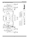
UPS System 1 - Primary Bypass
This light turns on when UPS System 1 is the selected Primary Bypass. When lit, the light indicates
the UPS Modules of both UPS systems are synchronizing to the bypass of UPS System 1, when sys-
tems are tied or in the process of transferring load.
UPS System 2 - Primary Bypass
This light turns on when UPS System 2 is the selected Primary Bypass. When lit, the light indicates
that the UPS Modules of both UPS systems are synchronizing to the bypass of UPS System 2, when
systems are tied or in the process of transferring load.
UPS System 1 - On Bypass
This light turns on when UPS System 1 is on Bypass.
UPS System 2 - On Bypass
This light turns on when UPS System 2 is on bypass.
Load 1 Circuit Breaker
These two lights indicate the OPEN (Red light) or CLOSED (Green light) state of the Load 1 circuit
breaker.
Load 2 Circuit Breaker
These two lights indicate the OPEN (Red light) or CLOSED (Green light) state of the Load 2 circuit
breaker.