


Operating Instructions
34
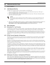
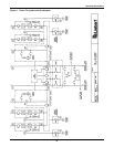
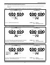
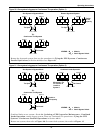
Figure 12 Transfer both load feeders to one UPS
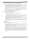
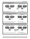
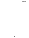
Figure 13 Both feeders on one system to normal operation
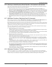
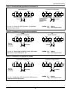
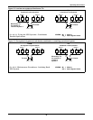
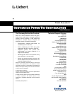
Figure 14 Transfer 100% load on one system to 100% load on a second system (a two-step operation)
M
1
M
1
SS
1
SS
2
M
2
M
2
System 1 System 2
Load 1 Load 2
Tie
FROM:
Normal Operation
Tie Open
See 4.2.4 - Isolating a UPS System for Maintenance -
Combined Loads Operation.
LEGEND: M
x
= Module
SS
x
= Static Bypass Switch
M
1
M
1
SS
1
SS
2
M
2
M
2
System 1 System 2
Load 1 Load 2
Tie
Tie Closed
TO:
Combined Loads Operation
Momentary Tie
for transfer of
Load 2 to
System 1
M
1
M
1
SS
1
SS
2
M
2
M
2
System 1 System 2
Load 1 Load 2
Tie
M
1
M
1
SS
1
SS
2
M
2
M
2
System 1 System 2
Load 1 Load 2
Tie
Tie Closed
See 4.2.6 - Returning an Isolated System to Normal
Operation - End Combined Loads Operation.
FROM:
Combined Loads Operation
TO:
Normal Operation
Tie Open
LEGEND: M
x
= Module
SS
x
= Static Bypass Switch
See 4.2.5 - Transfer of Load Between Two Systems.
LEGEND: M
x
= Module
SS
x
= Static Bypass Switch
M
1
M
1
SS
1
SS
2
M
2
M
2
System 1 System 2
Load 1 Load 2
Tie
Tie Closed
TO:
Combined Loads Operation on System 2
Momentary Tie for transfer
of Load 2 to System 2,
then Momentary Tie for
transfer of Load 1 to
System 2
M
1
M
1
SS
1
SS
2
M
2
M
2
System 1 System 2
Load 1 Load 2
Tie
Tie Closed
FROM:
Combined Loads Operation on System 1