


Operating Instructions
33
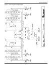
4.2.13 Operation Scenarios/Transfer Procedures
Refer to the section listed below each figure for the operational procedure to perform the function
indicated.
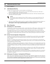
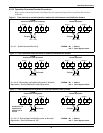
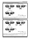
Figure 9 From start-up to normal operation, loads to be split between two distribution feeders
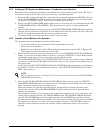
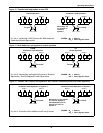
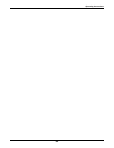
Figure 10 From combined loads operation to loads split between two feeders
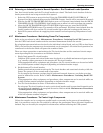
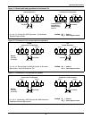
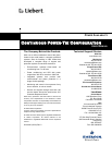
Figure 11 From continuous tied systems to loads split between two systems
M
1
M
1
SS
1
SS
2
M
2
M
2
System 1 System 2
Load 1 Load 2
Tie
M
1
M
1
SS
1
SS
2
M
2
M
2
System 1 System 2
Load 1 Load 2
Tie
Tie Open
See 4.1 - Initial System Start-Up.
FROM:
Initial Conditions Prior to Startup
TO:
Normal Operation
Tie Open
LEGEND: M
x
= Module
SS
x
= Static Bypass Switch
M
1
M
1
SS
1
SS
2
M
2
M
2
System 1 System 2
Load 1 Load 2
Tie
M
1
M
1
SS
1
SS
2
M
2
M
2
System 1 System 2
Load 1 Load 2
Tie
Tie Closed
See 4.2.6 - Returning an Isolated System to Normal
Operation - End Combined Loads Operation.
FROM:
Combined Loads Operation
TO:
Normal Operation
Tie Open
LEGEND: M
x
= Module
SS
x
= Static Bypass Switch
M
1
M
1
SS
1
SS
2
M
2
M
2
System 1 System 2
Load 1 Load 2
Tie
M
1
M
1
SS
1
SS
2
M
2
M
2
System 1 System 2
Load 1 Load 2
Tie
Tie Closed
See 4.2.11 - Returning Parallel Systems to Normal
Operation - End Continuous Tie.
FROM:
Continuous Tied Systems
TO:
Normal Operation
Tie Open
LEGEND: M
x
= Module
SS
x
= Static Bypass Switch
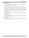
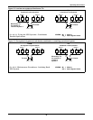
Continuous Tie
operation for
module out of
service