23
OPERATION
The best way to initially test and start-up the unit is to do it
without a load.
Initial System Start-up
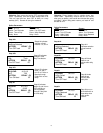
• Set the maintenance bypass rotary switch to the
maintenance position. Set the meter switch to the
Input L1-L2 position (units with meters)
• Locate customer’s critical load breakers. Verify that
all load breakers are in the off position. Close
customer supplied feed breaker. Power is now
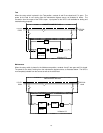
flowing through the maintenance bypass as illustrated
on page 19.
• Verify the L1-L2, L1-N and L2-N input voltages, with a
digital voltmeter (DVM), are as per the customer’s
specifications. The UPS and maintenance bypass
input and output voltages and frequency must be
the same for the system to operate according to
specifications.
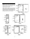
• Rotate the bypass switch to the Test position. Power
is now flowing through the maintenance bypass as
illustrated on page 19.
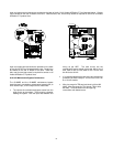
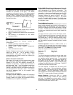
• Close the UPS battery breaker and input breaker, in
that order. The UPS should now be going through its
normal testing and start-up procedure. Follow UPS
LCD screen instructions.
• After the output breaker is closed and the ON button
is pressed, the unit should return to the Normal
Operation screen. Proceed to the meter screen on
the UPS LCD. Verify that the output voltage and
frequency is the same as the input voltage and
frequency.
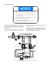
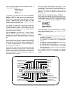
• With a DVM, verify that the there is no voltage
difference between the following points in the bypass
cabinet:
TB1 L1 to TB3 L1
TB1 L2 to TB3 L2
• Return the UPS LCD to the Normal Operation screen.
Transfer the UPS to bypass by placing the
bypass/UPS switch on the back of the unit in the
bypass position.
• Again with a DVM, verify that the there is no voltage
difference between the following points in the bypass
cabinet:
TB1 L1 to TB3 L1
TB1 L2 to TB3 L2
• Rotate the bypass switch to the On-Line position.
Transfer the Liebert UPStation S™ to the UPS mode
by placing the bypass/UPS switch on the back of the
unit in the UPS position and pressing the ON button
on the front of the unit. Power is now flowing through
the maintenance bypass as illustrated on page 18.
• The bypass switch is operating according to
specifications if no problems occurred during the
previous start-up steps.
• Transfer the UPS to bypass by placing the
bypass/UPS switch on the back of the unit in the
bypass position. Verify the L1-L2, L1-N and L2-N
output voltages, with a DVM, are as per the
customer’s specifications.
• The customer may now bring up their connected
critical loads. Always energize the load on bypass,
either UPS internal bypass or maintenance
bypass.
• After the load is up and operating, the UPS may now
be transferred on-line. Transfer the Liebert UPStation
S™ to the UPS mode by placing the bypass/UPS
switch on the back of the unit in the UPS position and
pressing the ON button on the front of the unit.
• Power is now flowing through the maintenance
bypass as illustrated on page 18. The load is
protected by UPS power.


