Installation
2
2.0 INSTALLATION
2.1 References
This document must be used together with site specific documentation and documentation for other
parts of the system.
2.2 Pre-Installation Checks
• Verify that the Liebert XDV voltage matches the available utility power. The serial tag with this
information is on the top of the unit, near the rear.
• Check the received materials to be sure all required assemblies and parts have been received. If
you discover any external damage, report it to the shipping company and your local Liebert repre-
sentative.
2.3 Parts Included With Liebert XDV
• Installation manual (this document)
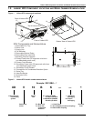
• Liebert XDV module
• Parts bag including
• IEC 10 ft. (3m) power cords, 2 (60Hz only; power cords for 50Hz are attached)
• 1/4 - 20 full thread 1" bolts, 4
• 1/4 inch locking hex nuts, 2
• mounting clips, 2
2.4 Installation Considerations
Each Liebert XDV module is to be securely mounted either on the top of a computer cabinet or rack or
above the heat-producing equipment. Mounting the Liebert XDV above the rack requires Liebert’s
optional mounting kit.
The units are designed to be mounted without modification on Liebert Foundation™ cabinets. Mount-
ing clips included with the Liebert XDV permit installation on other manufacturers’ cabinets and
racks. The clips also can be used with the Foundation for stronger attachment.
Determine whether the Liebert XDV includes the condensate detection option (factory-installed). This
option will require separate low voltage connections to a monitoring unit.
To minimize the possibility of condensation, insulate all piping between the Liebert XDV and the Lie-
bert XDP or Liebert XDC.
2.4.1 Room Preparation
The room should be well insulated and must have a sealed vapor barrier. The vapor barrier in the
ceiling and walls can be a polyethylene film. Paint on concrete walls and floors should contain either
rubber or plastic.
Outside or fresh air should be kept to a minimum when temperature and humidity must be tightly
controlled. Outside air adds to the cooling, heating, dehumidifying and humidifying loads of the site.
Doors should be properly sealed to minimize leaks and should not contain ventilation grilles.
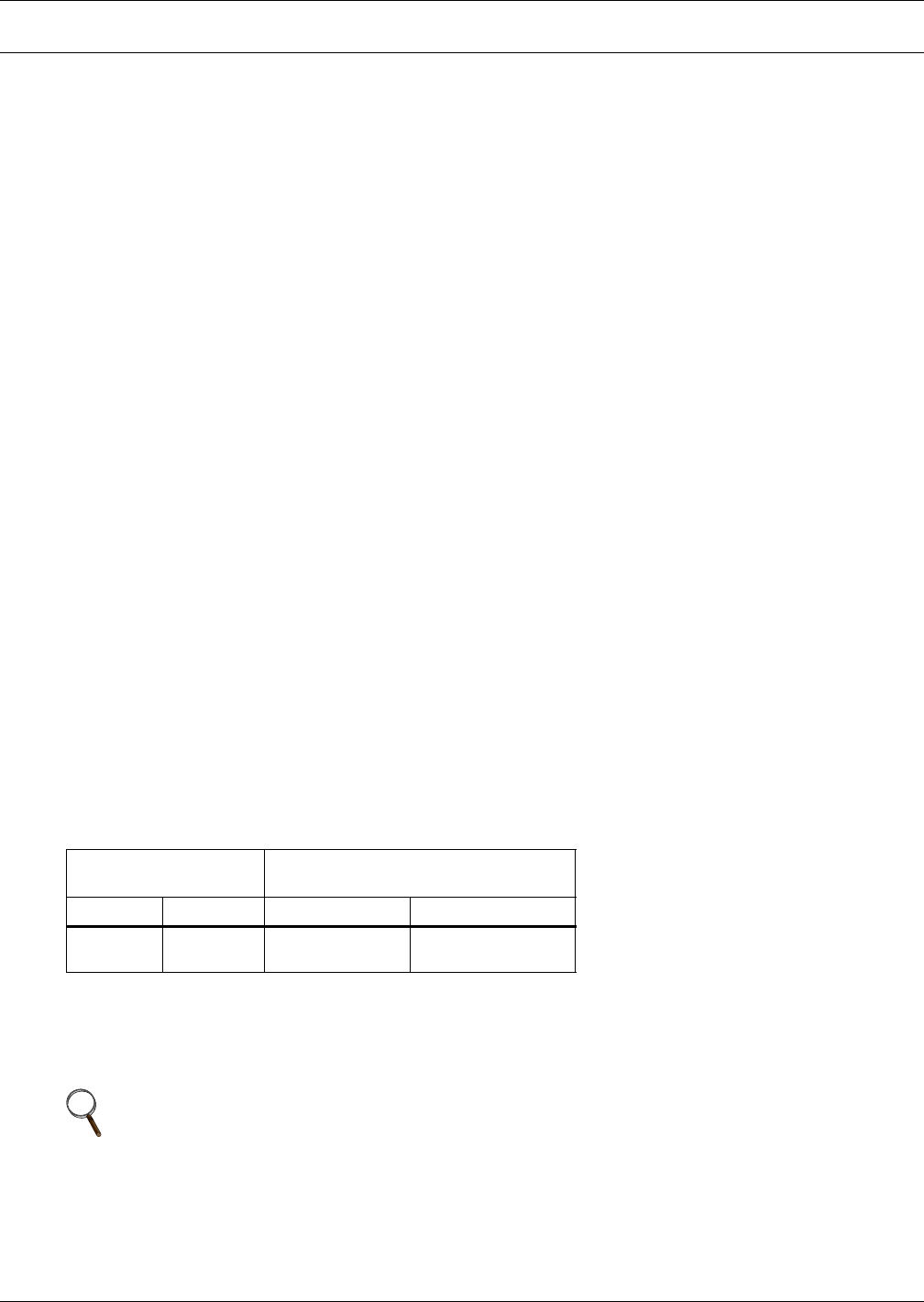
Table 1 Application limits
Input Voltage
Range of Return Air
Conditions to Unit
Minimum Maximum Dry Bulb Temp. Relative Humidity
-10% +10%
60° to 100°F
(16° to 38°C)
20% to 80%
NOTE
The vapor barrier is the single most important requirement for maintaining
environmental control in the conditioned space.


