


OPERATION
Power-Up Sequence
8 LDT-5525
CHAPTER 2
Power-Up Sequence
With the LDT-5525 Series Precision Temperature Controller connected to an AC
power source, pressing the POWER switch will supply power to the instrument
and start the power up sequence.
During the power-up sequence, the following takes place. For about two seconds
all indicators light up, and all of the 7-segment displays indicate "8". Then all
lamps are turned off for two seconds. Then, the sensor switch position is
displayed for two seconds. After this, the unit is configured to the state it was in
when the power was last shut off (except for the display mode which defaults to I
TE measurement). The adjust knob is always disabled at power up.
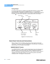
Introduction to the LDT-5525 Front Panel
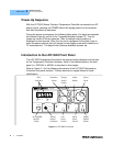
The LDT-5525 Temperature Controller's front panel contains displays and controls
for the Temperature Controller hardware. Each of the labeled areas on the front
panel (i.e. DISPLAY or MODE) is described in this chapter.
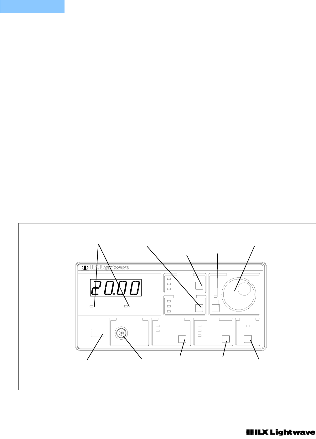
Refer to Figure 2.1 for the following discussions of the LDT-5525 Temperature
Controller front panel sections. The key words are in capital letters for quick
identification.
Figure 2.1 LDT-5525 Front Panel
Error Parameter Display Adjust Adjust
Indicators Switch Switch Enable Knob
Switch
SENSOR CA
L
TEMPERATURE CONTROLLER
TE OPENSENSOR OPEN
POWE
R
Ω
/V
100 k
Ω
/V
100 C/V
10 k
ANALOG OU
T
C2
C1
C
k
Ω
A
LDT-5525
T LIMIT
R
T
I
GAIN
TE
MOD
E
ON
OUTPU
T
ADJUS
T
DISPLA
Y
PARAMETE
R
I LIMIT
VIEW SET
SENSOR
I
TE
ENBL
AC POWER Analog CAL Mode Output
ON/Off Output Select Select On/Off
Switch Connector Switch Switch Switch