


OPERATION
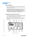
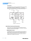
Introduction to the LDT-5525 Front Panel
10 LDT-5525
CHAPTER 2
The temperature is limited (via the sensor feedback) to the T LIMIT value. If the
sensor reads a temperature which is greater than T LIMIT, the I TE output will be
shut off.
The GAIN value is used to control the sensor feedback gain, and thus the
temperature settling time and overshoot. If the GAIN is set too low (1 is the lowest
setting) the TE cooler will take longer to reach the temperature set point. If the
GAIN is set too high (300 is the highest setting) the actual temperature may
oscillate around the set temperature.
The optimum GAIN setting depends on the type of TE cooler and temperature that
you are setting . Set the GAIN to its lowest value and then try increasing it until the
temperature oscillates around the set temperature. Then, reduce the GAIN one
step.
Parameter Setup
The PARAMETER switch is used to view and edit the parameters. Repeatedly
pressing the PARAMETER switch will cycle through the parameters.
When a parameter is selected for viewing, its value will remain on the display for
three seconds. If an adjustment is made to the parameter (by turning the adjust
knob) the three second timer will be restarted. Three seconds after the parameter
adjustment is done, the display will revert to the last measurement mode.
SENSOR CAL
These are the constants of the Steinhart-Hart equation that the user enters to
calibrate the TEC for different thermistors' temperature conversions. The
Steinhart-Hart equation is used to derive temperature from the non-linear
resistance of an NTC (Negative Temperature Coefficient) thermistor. For
information on setting C1 and C2 for thermistors, see Appendix A. For information
on thermistor selection and sensor current selection, see Appendix B.
When a linear sensor device (such as an AD590 or LM335) is used, a linear
equation is used. If a linear sensor's calibration is not known, set C1 = 0.00, C2 =
1.00. For more information on linear sensor calibration, see Appendix C.
The range of values for C1 and C2 are -9.99 to +9.99.
To read C1 or C2, press the CAL button until it sequences to the desired constant.
The C1 or C2 indicator will become lit to indicate which constant is selected. To
change the value, turn the ADJUST knob until the correct value is displayed.
Appendix A contains an explanation of the Steinhart-Hart equation and a
computer program to determine these values for any thermistor.