


OPERATION
General Operating Procedures
16 LDT-5525
CHAPTER 2
Resistance Mode Operation
You can operate the LDT-5525 Temperature Controller in several modes, constant
current (I TE), constant thermistor resistance (R), or constant temperature (T).
This example is for constant resistance (R) mode.
a Plug the LDT-5525 Temperature Controller into an AC power source supplying the
correct voltage and frequency for your unit (refer to the back panel for the correct
ratings).
b Turn on the LDT-5525 Temperature Controller. The OUTPUT stage will be off at
power up and the unit will automatically configure its parameters to the state which
existed when the power was last shut off.
c Press the ENBL switch in the ADJUST section of the front panel so that the indicator
is lit (adjustment enabled). Press the MODE switch until the R mode is selected.
d Check the setting of the SENSOR SELECT switch for the desired operation (10 µA or
100 µA). The sensor code will be displayed for two seconds during the power-up
sequence.
e Press the PARAMETER switch and check the setting of I LIMIT, T LIMIT, and GAIN.
Press the CAL switch and check the setting of C1 and C2 to insure that they are
compatible with the equipment you are using.
f Press the DISPLAY switch until the VIEW SET indicator is lit and check the set point
resistance. If it requires changing, turn the knob until the desired value is displayed.
g Turn the TEC output on by pressing the OUTPUT ON switch. The unit will
automatically control the thermistor to the set point resistance.
If the exact resistance is unknown (to control to a desired temperature), press the
DISPLAY switch to view the measured temperature. Readjust the resistance set
point and recheck the temperature until the desired result is attained.
Note: In some cases, a greater than 0.1
o
C temperature set point resolution may be
attained by using R mode with the appropriate resistance value.
If the mode is switched from R mode to T mode, the resistance set point will be lost. This is
becaused in T mode, the temperature set point is converted and also stored as a
resistance set point automatically.
h When the unit is powered off, the state of the unit at power-down is saved in non-
volatile memory.
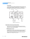
External Safety Switch Operation
On the TEC connector, pins 13 (TEMP LIMIT) and 15 (DIGITAL GND) form a type
of external safety switch (see Figure 2.3). These two pins are normally not
connected (open circuit), and must remain open for the TEC output to be on. If
there is a short circuit between these pins the TEC output will be disabled.
This circuit is useful for remote monitoring of temperature limit, and therefore is
labeled TEMP LIMIT on the back panel connector. This switch may be used with