


Section 2 Hardware Installation
10
Note: If video quality
deteriorates you can add
a VGA amplifier between
the fifth and the sixth
KVM switch to enhance
the VGA signal. (see
www.lindy.com for
appropriate products)
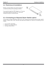
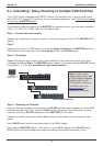
2.4 Cascading / Daisy Chaining of multiple KVM Switches
The P16-IP can be cascaded with LINDY P-Series CPU switches only. It should not be used
with LINDY PXT-Series CPU Switches. For all cascaded installations, the P16-IP should always
be used as the MASTER switch.
To connect an additional switch to the MASTER (or previous) switch, you must use a standard
(VGA + 2 x PS/2) 3-in-1 KVM cable, all connectors male.
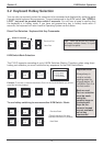
Step 1 - Connect the local console
Connect your keyboard, mouse and monitor to the console ports of the P16-IP MASTER KVM
Switch.
Step 2
Use one end of a 3-in-1 KVM cable to connect the daisy chain port of the MASTER/previous
KVM Switch and the other end to the console port of the next SLAVE switch.
Step 3 - Cascading
Repeat the previous step to daisy chain mores switches. Each individual switch in the chain
represents a different Bank. The MASTER switch is Bank 1 and each cascaded SLAVE follows
on as Bank 2, 3, 4 etc. to a maximum of eight banks/switches.
Step 4 – Resetting the Switches
After you have connected and switched on the SLAVE switches and computers, all of the KVM
switches must be reset. First, reset the SLAVE switch at the end of the daisy chain and then
reset all of the other SLAVE switches up to the MASTER P16-IP switch.
To reset the switch, press and hold the Bank button and P8 button on the front panel of the
switch.
Each SLAVE switch should now show a dash in its BANK display.
Now, reset the MASTER switch - it will show a 1 in the BANK display. Each SLAVE switch
BANK display will now change to a number according to its position in the daisy chain.
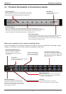
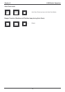
Bank 1 (Master)
Bank 3...to a maximum of 8
Cascading KVM Switches