


Chapter
2
6
Chapter 2: Getting to Know the Switch
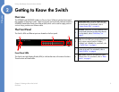
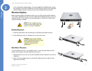
The Back Panel
Linksys One Ready Communications Solution
Uplink Ports
The Switch is equipped with 4 mini-GBIC uplink ports.
The Back Panel
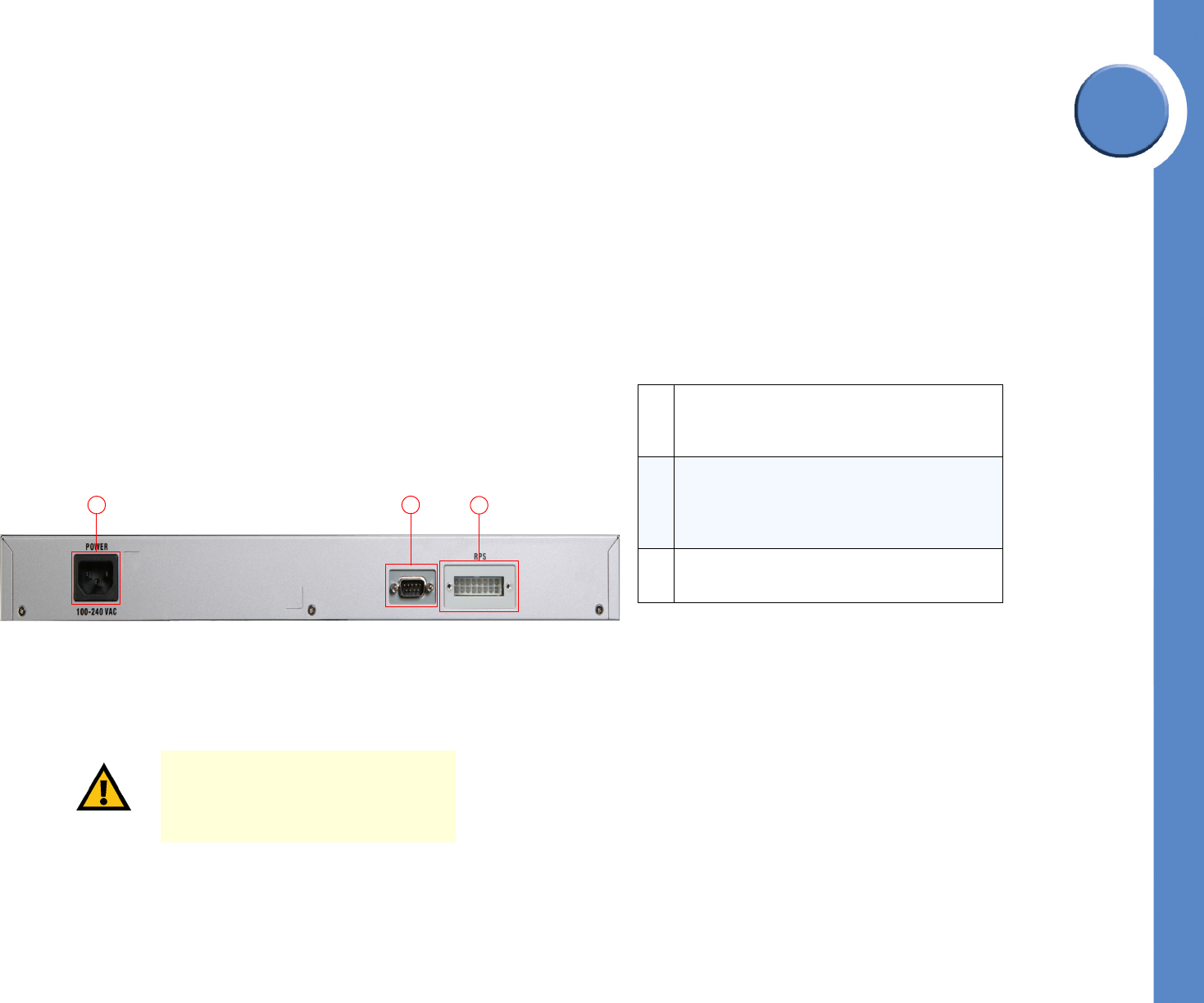
The power port is located on the back panel of the Ethernet switch.
Power Port
The 100-240 VAC power cord is connected to the Power port.
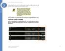
GBIC1-4 The Switch provides four mini-GBIC ports. The mini-GBIC port is a
connection point for a mini-GBIC expansion module, so the Switch can
be uplinked via fiber or copper to another switch. Each mini-GBIC port
provides a link to a high-speed network segment or individual
workstation at speeds of up to 1000Mbps.
Use the Linksys MGBT1, MGBSX1, or MGBLH1 mini-GBIC modules
with the Switch. The MGBSX1 and the MGBLH1 require fiber cabling
with LC connectors, while the MGBT1 requires a Category 5e Ethernet
cable with an RJ-45 connector.
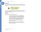
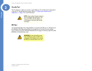
CAUTION: Only use the power cord
that is supplied with the Ethernet switch.
The unit may be damaged if the
incorrect power cord is used.
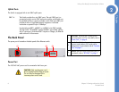
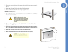
1
2
3
DC INPUT FOR REMOTE
POWER SUPPLY SPECIFIED
IN MANUAL +12V, 7.5A
1
Power Port. The Power port is where you will
connect the power cord. For more details, refer to
”Power Port,” on page 6.
2
Console Port. The Console port is where you can
connect a serial cable to a PC’s serial port for
configuration. For more details, refer to ”Console
Port,” on page 7
.
3
RPS Port. Redundant Power Supply (RPS) port. For
more details, refer to
”RPS Port,” on page 7.