


11
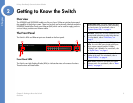
Chapter 3: Connecting the Switch
Connecting the Cables
Linksys One Ready Communications Solution
Chapter
3
Connecting the Cables
To connect network devices to the Ethernet switch, follow these instructions:
1. For 10/100Mbps devices, connect a Category 5 Ethernet network cable to one of the
numbered ports on the Ethernet switch. For a 1000Mbps device, connect a Category 5e
Ethernet network cable to one of the uplink ports on the Ethernet switch.
2. Connect the other end to a PC or other network device.
3. Repeat steps 2 and 3 to connect additional devices.
4. If you are using the mini-GBIC port, then insert the mini-GBIC module to the mini-GBIC
port. For detailed instructions, refer to the documentation supplied with the mini-GBIC
module.
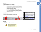
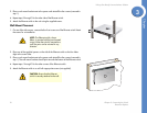
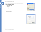
5. If you use the console interface to configure the Ethernet switch, then connect the
supplied serial cable to the console port (located on the back of the Ethernet switch), and
tighten the captive retaining screws. Connect the other end to your PC’s serial port. (The
PC must be running VT100 terminal emulation software, such as HyperTerminal.)
6. Connect the supplied power cord to the power port, and plug the other end into an
electrical outlet.
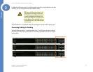
7. Power on the network devices connected to the Ethernet switch. Each active port’s
corresponding Act/Link LED will light up on the Ethernet switch. If a port has an active
Gigabit connection, then its corresponding Gigabit LED will also light up.
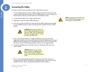
CAUTION: Observe the orientation of
the mini-GBIC module before inserting it
into a mini-GBIC port. The bottom mini-
GBIC ports are upside down in relation
to the top mini-GBIC ports.
CAUTION: Make sure you use the
power cord that is supplied with the
Ethernet switch. Use of a different
power cord could damage the Ethernet
switch.
NOTE: If connecting an Ethernet switch
to an SVR3000 router, connect it to a
Cascade port on the SVR3000.