


Chapter
3
10
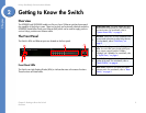
Chapter 3: Connecting the Switch
Placement Options
Linksys One Ready Communications Solution
3. Place a rack mount bracket next to the spacer and reinstall the four screws (removed in
step 1).
4. Repeat steps 2 through 3 for the other side of the Ethernet switch.
5. Attach the Ethernet switch to the rack using the supplied screws.
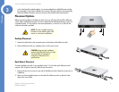
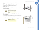
Wall-Mount Placement
1. On one of the side corners, remove the four front screws on of the Ethernet switch. Retain
the screws for re-installation.
2. Place one of the supplied spacers on the side of the Ethernet switch so the four holes
align to the screw holes.
3. Place a rack mount bracket next to the spacer and reinstall the four screws (removed in
step 1). The wall mount brackets should point towards the bottom of the Ethernet switch.
4. Repeat steps 1 through 3 for the other corners of the Ethernet switch.
5. Attach the Ethernet switch to a wall with appropriate screws (not supplied).
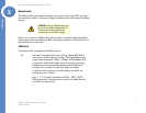
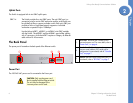
NOTE: The Ethernet switch, shown
below, is mounted with the ports located
on top. When the switch is mounted to a
wall, the ports can be oriented in any
direction.
CAUTION: Ensure that the Ethernet
switch is securely attached to the wall.