


5
Installation
Wireless-G Business Ethernet Bridge
Chapter 4
Chapter 4:
Installation
Overview
This chapter explains how to place and connect the Bridge.
Depending on your application, you might want to set
up the device first before mounting the device. Refer to
“Chapter 6: Advanced Configuration”.
Connection
There are two ways to install the Bridge: using Power
over Ethernet (PoE), or using the supplied power adapter.
Follow the appropriate procedure below.
Power over Ethernet
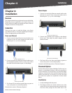
Connect one end of an Ethernet network cable to the 1.
LAN port on your PC, then connect the other end to
Ethernet port 1, 2, 3, or 4 on the Bridge.
Connect the Bridge to a PC
Connect one end of an Ethernet network cable to your 2.
PoE-equipped network switch or router, and connect
the other end of the cable to port 5 on the Bridge.
Connect the PoE Cable
The Power LED on the front panel lights up green as 3.
soon as the power is connected properly.”
Proceed to the section, “Placement Options.”
Power Adapter
Connect one end of an Ethernet network cable to the 1.
LAN port on your PC, then connect the other end to
Ethernet port 1, 2, 3, 4, or 5 on the Bridge.
Connect the Bridge to a PC
Connect the included power adapter to the Bridge’s 2.
Power port. Then plug the power adapter into an
electrical outlet.
Connect the Power Adapter
The Power LED on the front panel lights up green as 3.
soon as the power is connected properly.”
Proceed to the following section, “Placement Options.”
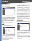
Placement Options
There are three ways to place the Bridge. The first way is to
place it on a horizontal surface, so that it sits securely on
its four rubber feet. The second way is to stand the Bridge
upright on a horizontal surface by attaching the included
stands. The third way is to mount it on a wall. The stand
and wall-mount options are explained in further detail
below.
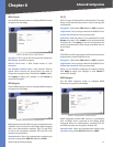
Stand Option
Locate the Bridge’s left side panel. 1.
The Bridge includes two stands. Position one of the 2.
stands with its two large prongs facing outward, then
insert the short prongs into the small slots in the