


3.75 pc 10.25 pc 11.25 pc 38.25 pc
4.333 pc
48.583 p
c
52.5 pc
34.5 pc
44.25 pc
2-4 Installing the LSIU160
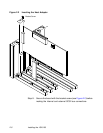
2.2.2 Inserting the Host Adapter
For safe and proper installation, you will need the user’s manual supplied
with your computer. Perform the following steps to install the LSIU160.
Step 1. Ground yourself before removing this host adapter board.
Step 2. Remove the LSIU160 from the packing and check that it is not
damaged.
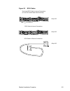
An example of this host adapter board is shown in Figure 2.1.
A more detailed drawing is located in Figure A.1.
Step 3. Switch off the computer and unplug power cords for all
components in your system.
Step 4. Remove the cover from your computer per the instructions in
the user’s manual for your system to access the PCI slots.
Caution: Ground yourself by touching a metal surface before
removing the cabinet top. Static charges on your body can
damage electronic components. Handle plug-in boards by
the edge; do not touch board components or gold
connector contacts. The use of a static ground strap is
recommended.
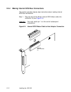
Step 5. Locate the slots for PCI plug-in board installation.
Refer to the user’s manual for your computer to confirm the
location of the PCI slots.
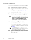
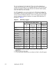
The LSIU160 requires a 32-bit or 64-bit PCI slot that allows bus
master operation. If a 32-bit PCI slot is used, bits [31:1] of the
J1 connector are inserted while bits [64:32] remain uninserted.
See Figure 2.2.
Note: For the LSIU160 to function as a 64-bit device, it must
inserted in a 64-bit PCI slot. If the LSIU160 is inserted in a
32-bit PCI slot, it will function as a 32-bit device.
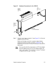
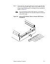
Step 6. Remove the blank bracket panel on the back of the computer
aligned with the PCI slot you intend to use.
Save the bracket screw.