


3.75 pc 10.25 pc 11.25 pc 38.25 pc
4.333 pc
48.583 p
c
52.5 pc
34.5 pc
44.25 pc
A-4 Technical Specifications
A.2 Operational Environment
The LSIU160 is designed for use in PCI computer systems with an
ISA/EISA bracket type. SDMS operates the board, but the design of the
board does not prevent the use of other software. An on-board flash
memory device is provided to allow BIOS code and open boot code
support through PCI and a serial EEPROM.
A.2.1 The PCI Interface
The PCI interface operates as a 64-bit DMA bus master. The connection
is made through edge connector J1, which provides connections on both
the front and back of the board. The signal definitions and pin numbers
conform to the PCI Local Bus Specification Revision 2.2 standard.
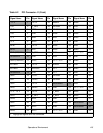
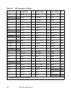
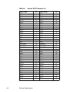
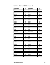
Table A.2 and Table A.3 show the signal assignments. The PCI portion
of the LSI53C1010 device is powered from the onboard +3.3 V regulator.
Note: The +3.3 V pins are tied together and decoupled with high
frequency bypass capacitors to ground. No current from
these 3.3 V pins is used on the board. The board derives
power from the +5 V pins, directly and through a 3.3 V
voltage regulator. The PCI +3 V/+5 V pins are used to
differentiate between a 5 V or a 3.3 V PCI environment.