


3.75 pc 10.25 pc 11.25 pc 38.25 pc
4.333 pc
48.583 p
c
52.5 pc
34.5 pc
44.25 pc
Detailed Installation Procedure 2-5
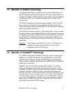
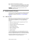
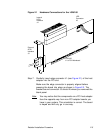
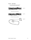
Figure 2.1 Hardware Connections for the LSIU160
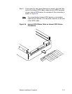
Step 7. Carefully insert edge connector J1 (see Figure 2.1) of the host
adapter into the PCI slot.
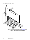
Make sure the edge connector is properly aligned before
pressing the board into place as shown in Figure 2.2. The
bracket around connector J3 should fit where you removed the
blank panel.
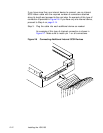
Note: You may notice that the components on a PCI host adapter
face the opposite way from non-PCI adapter boards you
have in your system. This orientation is correct. The board
is keyed and will only go in one way.
LED
Internal
External
LSIU160
SCSI
Interface
J4
Connector
J6
SCSI
Interface
J3
J1 to PCI Mainboard