CMOS Setup / IDE Configuration
EPM-4 Reference Manual Configuration / Operation – 11
CMOS Setup / IDE Configuration
IDE
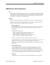
The Lynx has a single IDE channel to connect up to two hard disks, CompactFlash modules
or CD-ROM drives. This basic IDE interface operates using PIO mode 0, resides on the ISA
bus, and does not support the drive address register at I/O address 3F7h. It has been tested
successfully on a wide variety of operating systems.
IDE
SETUP
IDE devices include hard disk drives, CD-ROM drives, and some CompactFlash modules.
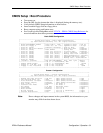
There are 3 fields in the Basic CMOS Configuration screen that are relevant to IDE setup:
IDE Drive Geometry, Drive Assignment Order, and Boot Order.
IDE Drive Geometry
Most desktop PCs have two IDE channels, each capable of supporting two IDE devices
in a slave/master configuration or a single IDE device in a single (or master only)
configuration.
In the IDE Drive Geometry list:
IDE 0 corresponds to primary channel, master/single drive.
IDE 1 corresponds to primary channel, slave drive.
IDE 2 corresponds to secondary channel, master/single drive.
IDE 3 corresponds to secondary channel, slave drive.
The Lynx uses the first IDE channel only. IDE 2 and IDE 3 are unused
All modern IDE devices use LBA mode. When setting up an IDE device, leave the drive
geometry set to LBA mode unless your hard drive requires a different mode.
CD-ROM drives that will be used as boot devices should be set accordingly in the Drive
Geometry list.
Drive Assignment Order
After a hard drive has been declared in the IDE Drive Geometry field, it must be
assigned a DOS drive letter, even if you are not using the DOS operating system.
Normally, "Drive C:" will be assigned to the IDE device that you wish to boot from.
Do not attempt to assign a drive letter to a CD-ROM drive. The drivers required to use
these devices will automatically assign a drive letter to the device when loaded.
Boot Order
This field allows you to specify the order in which the BIOS looks for boot devices.


