Ethernet Interface
Reference – 32 EPM-4 Reference Manual
Ethernet Interface
The EPM-4 features an industry-standard 10baseT / 100baseTX Ethernet interface based on the
Intel 82551ER Ethernet controller. This PCI based interface chip is widely supported. Drivers are
readily available to support a variety of operating systems such as QNX, VxWorks and other
RTOS vendors.
BIOS
CONFIGURATION
The Ethernet interface shares PC/104-Plus interrupt “INTC”. The CMOS Setup screen is used to
select the IRQ line routed to INTC*.
S
TATUS LED
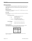
Two colored LEDs (D1) located next to the RJ-45 connector provide an indication of the Ethernet
status as follows:
Green LED (Link / Activity)
• ON Active Ethernet cable plugged into J4.
No Tx/Rx data activity.
• OFF Cable not plugged into J4
Cable not plugged into active hub
• BLINKING Active Ethernet cable plugged into J4.
Tx or Rx data activity detected on the cable
Yellow LED (Speed)
• ON 100baseTx (Fast) detected on Ethernet cable.
• OFF 10BaseTx (Slow) detected on Ethernet cable.
E
THERNET CONNECTOR
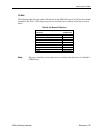
A board-mounted RJ-45 connector is provided to make connection with category 5 Ethernet
cable. The Ethernet controller will autodetect 10BaseT/100BaseTX connections.
Table 7: RJ45 Ethernet Connector
J4
Pin
Signal
Name
Function
4 IGND Isolated Ground
5 IGND Isolated Ground
6 R– Receive Data –
3 R+ Receive Data +
7 IGND Isolated Ground
8 IGND Isolated Ground
2 T– Transmit Data –
1 T+ Transmit Data +
This device is protected against ESD damage by IEC 61000-4-2 rated transient voltage
suppressor components.


