


Marathon Monitors Inc.
AACC 2000 Carbon Nov. 1, 1997
84
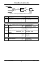
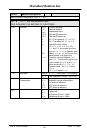
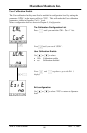
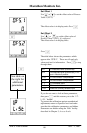
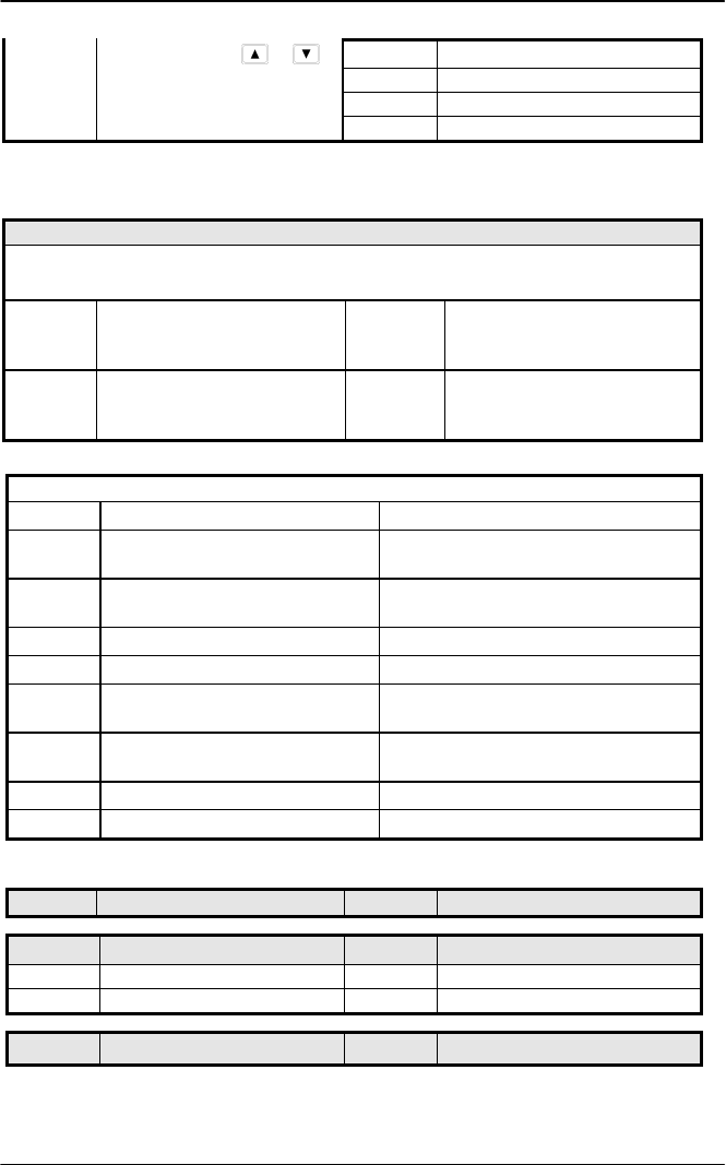
Select ‘YES’ with or
YES
Start calibration
Wait for calibration to
buSy
Busy calibrating
complete.
donE
PV input calibration completed
FAIL
Calibration failed
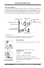
Note. When a DC input module is installed for the first time, or there is a requirement to change one,
then the microprocessor in the controller needs to read the factory calibration data stored in the module.
Select ‘FACt’ as the calibration value. Step to ‘GO’ and start calibration.
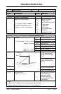
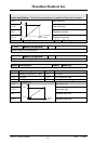
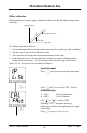
DC Output Calibration
The following parameters apply to DC output modules ie for rcAL = 1A.Hi to 3A.Lo
cAL.H
Output Calibration High
0 0 = Factory set calibration.
Trim value until output = 9V, or
18mA
cAL.L
Output Calibration Low
0 0 = Factory set calibration.
Trim value until output = 1V, or
2mA
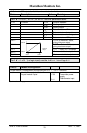
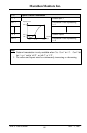
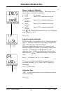
User calibration
UCAL User calibration enable Yes/no
pt1.L
Low calibration point for Input 1 The factory calibration point at which the
low point offset was performed.
pt1.H
High calibration point for Input 1 The factory calibration point at which the
high point offset was performed.
OF1.L
Offset Low for Input 1 Calculated offset, in display units.
OF1.H
Offset High for Input 1 Calculated offset, in display units.
pt2.L
Low calibration point for Input 2 The factory calibration point at which the
low point offset was performed.
pt2.H
High calibration point for Input 2 The factory calibration point at which the
high point offset was performed.
OF2.L
Offset Low for Input 2 Calculated offset, in display units.
OF2.H
Offset High for Input 2 Calculated offset, in display units.
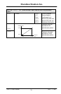
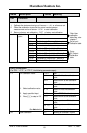
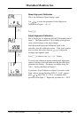
Name Description Values Meaning
PASSPASS
Password configuration
ACC.P
FuLL or Edit level password
cnF.P
Configuration level password
ExitExit
Exit configuration
no/YES