


MM6854/64 Dual Band GSM Data Modem
Issue 1.0 ME 820047
03/00 Page 7
4 OPERATION
4.1 Introduction
This section covers the simple operation of the modems. It provides the relevant information for the
user to get the modem up and running.
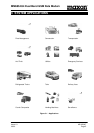
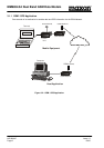
A +9V to +28VDC power supply will be required, together with a Windows 95 PC, installed with Hyper
Terminal, or similar package, a CA8360 power cable, a CA8401 antenna and a CA8361 PC serial
cable.
4.2 Network Connection
It is necessary to obtain a SIM from your chosen Network Provider. This SIM must be suitable for
Data service.
All information needed to connect you to the network and to initiate billing for your calls is stored in the
gold-plated area of the SIM card, along with the names, numbers and messages you have entered
into the phone book, or received.
To prevent either, the loss of information or corruption of information, avoid touching the gold area and
do not place the SIM near electrical or magnetic fields.
A damaged SIM will not allow you to access the GSM network.
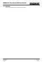
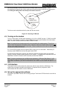
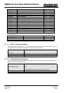
4.2.1 Inserting the SIM card
The SIM card will probably be supplied in a cardholder and will need to be carefully pressed free,
before fitting.
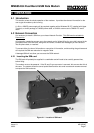
The modem must not be powered. If the 25 way D-type connector is removed, this ensures that this is
the case. The modem should be turned upside down and the two small countersunk screws removed
to expose the SIM card area.
Figure 4-1 - Location of SIM card