AT INTERFACE DESCRIPTION
5 – 1
SECTION 5
AA
AA
A
T Interface DescriptionT Interface Description
T Interface DescriptionT Interface Description
T Interface Description
Interface ConnectorInterface Connector
Interface ConnectorInterface Connector
Interface Connector
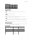
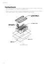
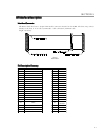
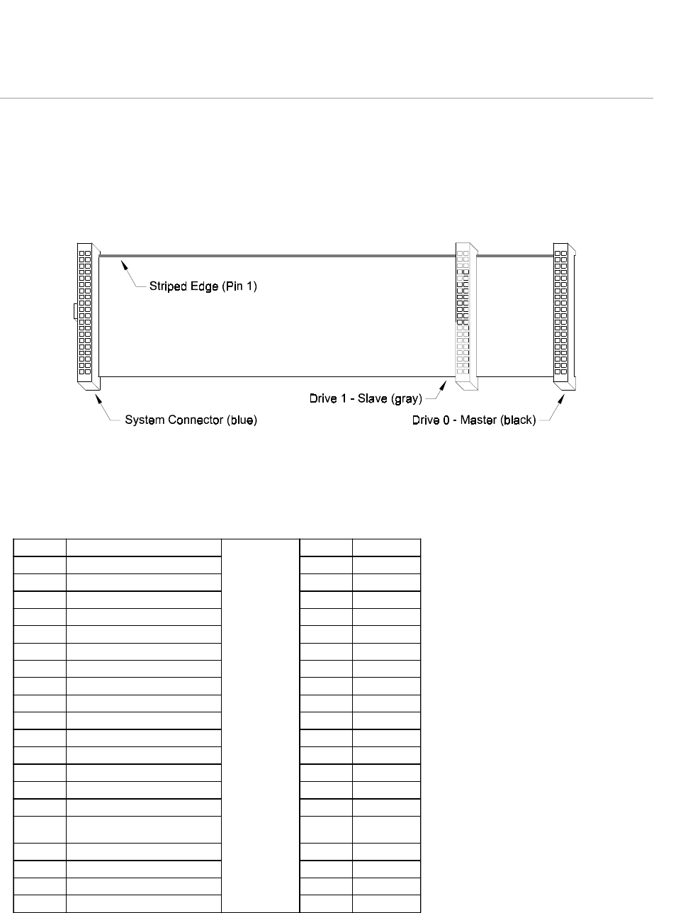
All Maxtor hard drives have a 40-pin ATA interface connector mounted on the PCBA. The drive may connect
directly to the host; or it can also accommodate a cable connection (maximum cable
length: 18 inches).
Figure 5-1
Data Connector
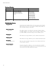
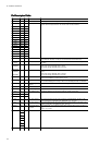
Pin Description SummaryPin Description Summary
Pin Description SummaryPin Description Summary
Pin Description Summary
PIN SIGNAL PIN SIGNAL
01 Reset - 02 Ground
03 DD7 04 DD8
05 DD6 06 DD9
07 DD5 08 DD10
09 DD4 10 DD11
11 DD3 12 DD12
13 DD2 14 DD13
15 DD1 16 DD14
17 DD0 18 DD15
19 Ground 20 (keypin)
21 DMARQ 22 Ground
23 DIOW -:STOP 24 Ground
25 DIOR -:HDMARDY:HSTROBE 26 Ground
27 IORDY:DDMARDY:DSTROBE 28 CSEL
29 DMACK - 30 Ground
31 INTRQ 32
IOCS16
Obsolete
33 DA1 34 PDIAG -
35 DA0 36 DA2
37 CS0 - 38 CS1 -
39 DASP - 40 Ground


