


HOST SOFTWARE INTERFACE
6 – 5
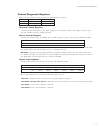
Control Diagnostic Registers
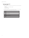
These I/O port addresses reference three Control/Diagnostic registers:
TROPO/IDAERETIRW
h6F3sutatSetanretlAlortnoCksiDdexiF
h7F3tupnIlatigiDdesutoN
Alternate Status Register
Contains the same information as the Status register in the Task File. However, this register may be read at
any time without clearing a pending interrupt.
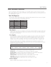
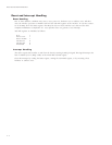
Device Control Register
Contains the software Reset and Enable bit to enable interrupt requests to the host. Bit definitions follow:
76543210
00000 TSRSNEI0
teseRelbanEQRI
Reset – Setting the software Reset bit holds the drive in the reset state. Clearing the bit re-enables the drive.
The software Reset bit must be held active for a minimum of 5 µsec.
IRQ Enable
– Setting the Interrupt Request Enable to 0 enables the IRQ 14 signal to the host. When this bit is set
to 1, IRQ14 is tri-stated, and interrupts to the host are disabled. Any pending interrupt occurs when the bit is set to 0.
The default state of this bit after power up is 0 (interrupt enabled).
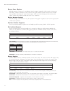
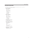
Digital Input Register
Contains information about the state of the drive. Bit definitions follow:
76543210
xGW-3SH-2SH-1SH-0SH-1SD-0SD
devreseR
etaG
daeH
3tceleS
daeH
2tceleS
daeH
1tceleS
daeH
0tceleS
evirD
1tceleS
evirD
0tceleS
Bit 7 of the host data bus is not driven when this register is read.
-Write Gate
– Reflects the state of the active low write gate signal on the drive.
-Head Select 3 through -Head Select 0
– Represents the ones complement of the currently selected head number.
-Drive Select 1
– Is 0 if drive 1 selected; 1 otherwise.
-Drive Select 0
– Is 0 if drive 0 selected; 1 otherwise.