


PCI-CTR05 User's Guide Specifications
Counter
Refer to the CTS9513-2 data sheet for complete 9513 specifications and operating modes. The SAVE
command for the CTS9513 device does not behave predictably when using clocks which are not
synchronous with the logic timing. The CTS9513-2 data sheet is available on our web site at
www.mccdaq.com/PDFmanuals/9513A.pdf
.
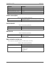
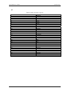
Table 4-3. Counter specifications
Parameter Conditions
Counter type 9513
Configuration One 9513 device. Five up/down counters, 16 bits each.
Compatibility 5V/TTL
The 9513 device is programmable for:
Clock source Software selectable:
External:
Counter 1-5 clock inputs
Counter 1-5 gate inputs
Internal:
Terminal count of previous counter
X2 clock frequency scaler
Gate: Software selectable source:
External (default logic high):
Active high or low level or edge, counter 1 – 5 gate input
Active high level previous gate or next gate
All external gate signals (CTRxGATE) individually pulled up
through 10K resistors to +5V.
Internal:
Active high previous counter terminal count
No gating.
Output: Software selectable:
Always low
High pulse on terminal count
Low pulse on terminal count
Toggle on terminal count
Inactive, high impedance at user connector counter # output.
Osc Out Software selectable source:
Counter # input
Gate # input
Prescaled clock source (X2 clock frequency scaler)
Software selectable divider:
Division by 1-16
Software selectable enable:
On or low impedance to ground.
Clock input frequency 6.8 MHz max (145 nS min period)
X2 clock input sources Software selectable:
1.0 MHz (10 MHz Xtal divided by 10)
5.0 MHz (10 MHz Xtal divided by 2)
3.3 MHz (33 MHz PCI clock divided by 10)
1.67 MHz (33 MHz PCI clock divided by 20)
X2 clock frequency scaler
BCD scaling (X2 divided by 10, 100, 1000 or 10000) or Binary scaling
(X2 divided by 16, 256, 4096 or 65536)
High pulse width (clock input) 70 ns min
Low pulse width (clock input) 70 ns min
Gate width high 145 ns min
Gate width low 145 ns min
4-2