


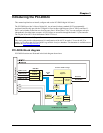
PCI-DIO24 User's Guide Installing the PCI-DIO24
Connecting the board for I/O operations
Connectors, cables – main I/O connector
Table 2-1
Table 2-1. Board connectors, cables, and accessory equipment
lists the board connector type, applicable cables, and compatible accessory products for the PCI-
DIO24.
Connector type 37-pin D-type
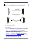
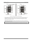
Compatible cables C37FF-x unshielded ribbon cable. x = length in feet. (see Figure 2-2)
C37FFS-x cable shielded round cable. x = length in feet. (see Figure 2-3)
Compatible accessory products
(with the C37FF-x or C37FFS-x cable)
SCB-37
CIO-MINI37
CIO-MINI37-VERT
CIO-ERB08
CIO-SERB08
CIO-ERB24
CIO-SPADE50
SSR-RACK08
SSR-RACK24
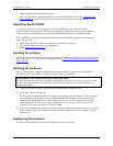
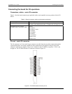
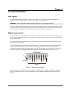
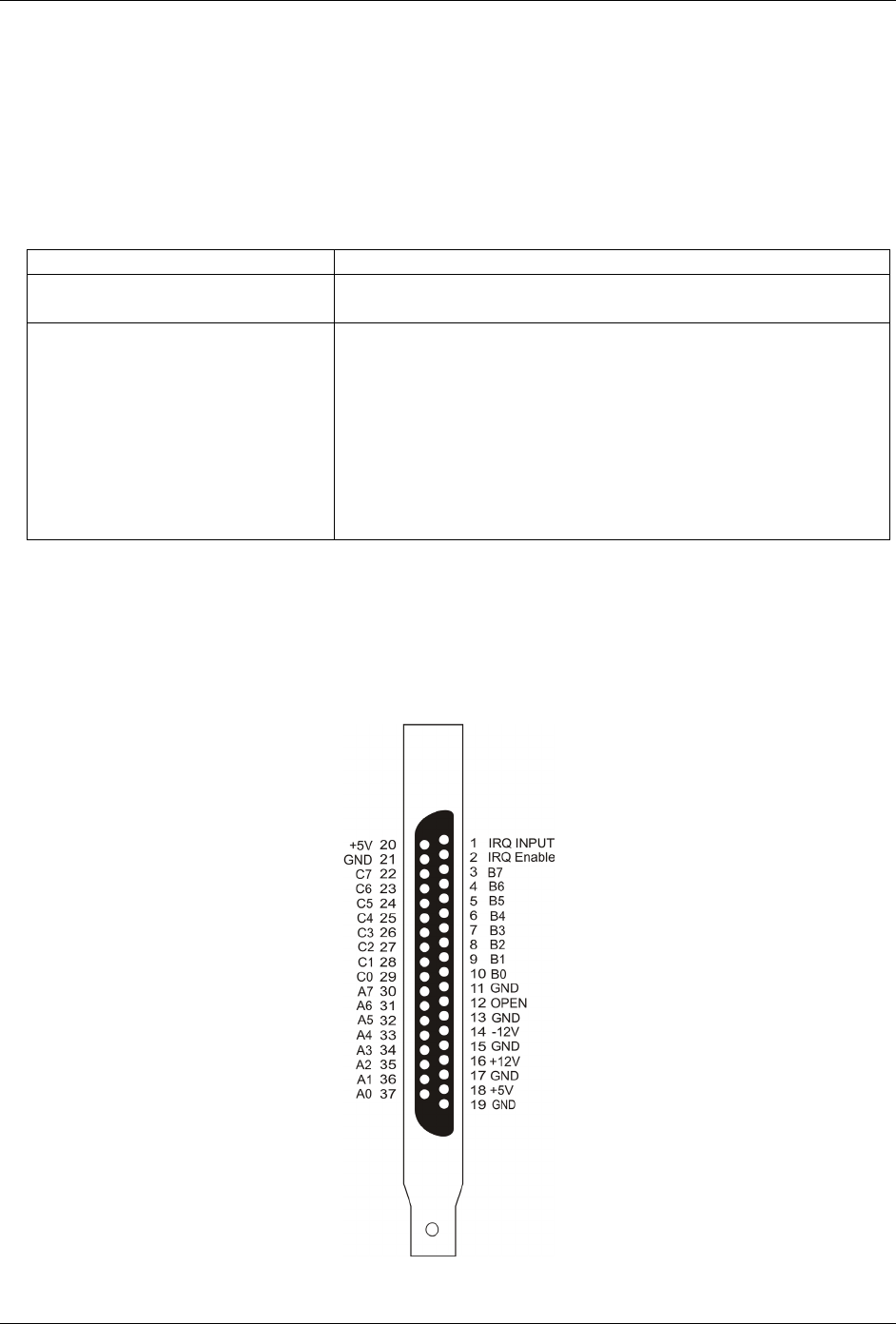
Pin out – main I/O connector
The I/O connector is a 37-pin, male D-type connector accessible from the rear of the computer through the
expansion backplate. The signals available are direct connections to the digital I/O chips as well as the
computer's internal power supplies. The pin out is identical to the CIO-DIO24, except that −5 VDC is not
brought out. The PCI-DIO24 board's I/O connector is shown in Fi . gure 2-1
Figure 2-1. PCI-DIO24 board connector pin out
2-3