


PCI-DIO24 User's Guide Functional Details
2.2 K SIP installed for pull-up
2.2 K SIP
Dot indicates the
common line
+5 VDC
HI
LO
(GND)
n7
User Connector
Digital I/O Lines
n5
n4
n3
n2
n1
n0
n6
COM
Digital
I/O Port
n = A, B, or C
+5 VDC
2.2 K SIP installed for pull-down
2.2 K SIP
Dot indicates the
common line
HI
LO
(GND)
n7
User Connector
Digital I/O Lines
n5
n4
n3
n2
n1
n0
n6
COM
Digital
I/O Port
n = A, B, or C
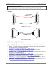
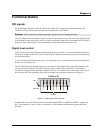
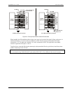
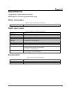
Figure 4-2. Pull-up and pull-down resistor SIP schematic
When installed, the SIP establishes either a high or low logic level at each of the eight I/O lines on the port. At
each board location, A, B, and C, there are 10 holes in a line. The hole on one end is marked "HI" and is
connected to +5V. The other end is marked "LO" and is connected to GND. The eight holes in the middle
connect to eight lines of the port, A, B or C.
To pull-up lines, orient the SIP with the common pin (dot) toward the HI end; to pull-down, install the resistor
with the common pin in the LO hole.
Note:
We recommend using 2.2KΩ SIPs (MCC part number SP-K2.29C). Use a different value only if necessary.
4-2