


Chapter 1
Introducing the PCI-DIO24
This manual explains how to install, configure and use the PCI-DIO24 digital I/O board.
The PCI-DIO24 provides 24 lines of digital I/O. An on-board, industry standard 82C55 programmable
peripheral interface chip provides the 24 digital I/O lines in three eight-bit ports (Port A, Port B, and Port C).
Port C can be further divided into two four-bit ports (Port C-HI and Port C-LO). You can configure each port
independently for either input or output. All 24 I/O lines are accessible through the board's 37-pin connector.
The I/O pins of an 82C55 are bi-directional CMOS TTL level.
82C55 mode 1 or mode 2 operation
This user's guide provides information on I/O configuration of the 82C55 in mode 0. To use the 82C55 in
modes 1 or 2, refer to the 82C55A CMOS Programmable Interface datasheet. This document is available on our
web site at www.mccdaq.com/82C55.
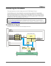
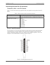
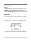
PCI-DIO24 block diagram
PCI-DIO24 functions are illustrated in the block diagram shown here.
PCI
Controller
BADR1
Boot
EEPROM
Control
Registers
Decode/Status
Bus
Timing
Controller FPGA and logic
Local Bus
PCI BUS (5V, 32-bit, 33 MHZ)
Control
Bus
Interrupt
Control
+5V
+12V
-12V
BADR2
Interrupt
PORT A
Control
PORT A (7:0)
8255 DIO
PORT B (7:0)
PORT CH (3:0)
PORT B
PORT CH
PORT CL
PORT CL (3:0)
IRQ INPUT
IRQ ENABLE
37-Pin I/O Connector
1-1