


Chapter 3
Functional Details
External components
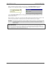
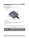
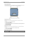
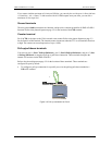
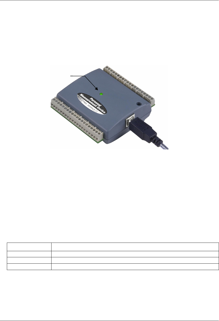
The PMD-1024HLS has the following external components, as shown in Figure 3-1.
USB connector
LED
Screw terminal banks (2)
Screw terminal
pins 1 to 20
LED
Screw terminal
pins 21 to 40
USB
connector/cable
Figure 3-1. PMD-1024HLS external components
USB connector
The USB connector is on the right side of the PMD-1024HLS housing. This connector provides +5 V
power and communication. The voltage output is system-dependent, and may be less than +5 V. No
external power supply is required.
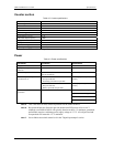
LED
The LED on the front of the housing indicates the communication status of the PMD-1024HLS. It uses up
to 5 mA of current and cannot be disabled. explains the function of the PMD-1024HLS LED. Table 3-1
Table 3-1 LED illumination
LED Illumination Indication
Steady green The PMD-1024HLS is connected to a computer or external USB hub.
Blinks continuously Data is being transferred.
Blinks three times Initial communication is established between the PMD-1024HLS and the computer.
3-1