


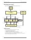

PMD-1024HLS User's Guide Functional Details
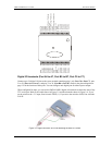
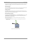
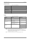
To configure a pull-down connection for a specific port, wire the pull-up/pull-down terminal to a
GND terminal.
Figure 3-6. Pull-down connection for Port A
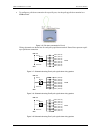
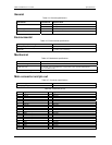
Wiring schematics are shown here for each pull-up/pull-down terminal. Dotted lines represent a pull-
up or pull-down connection.
USB +5 V
DIO 0 (Port A0)
Figure 3-7. Schematic showing Port A pull-up/pull-down wiring options
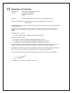
Figure 3-8. Schematic showing Port B pull-up/pull-down wiring options
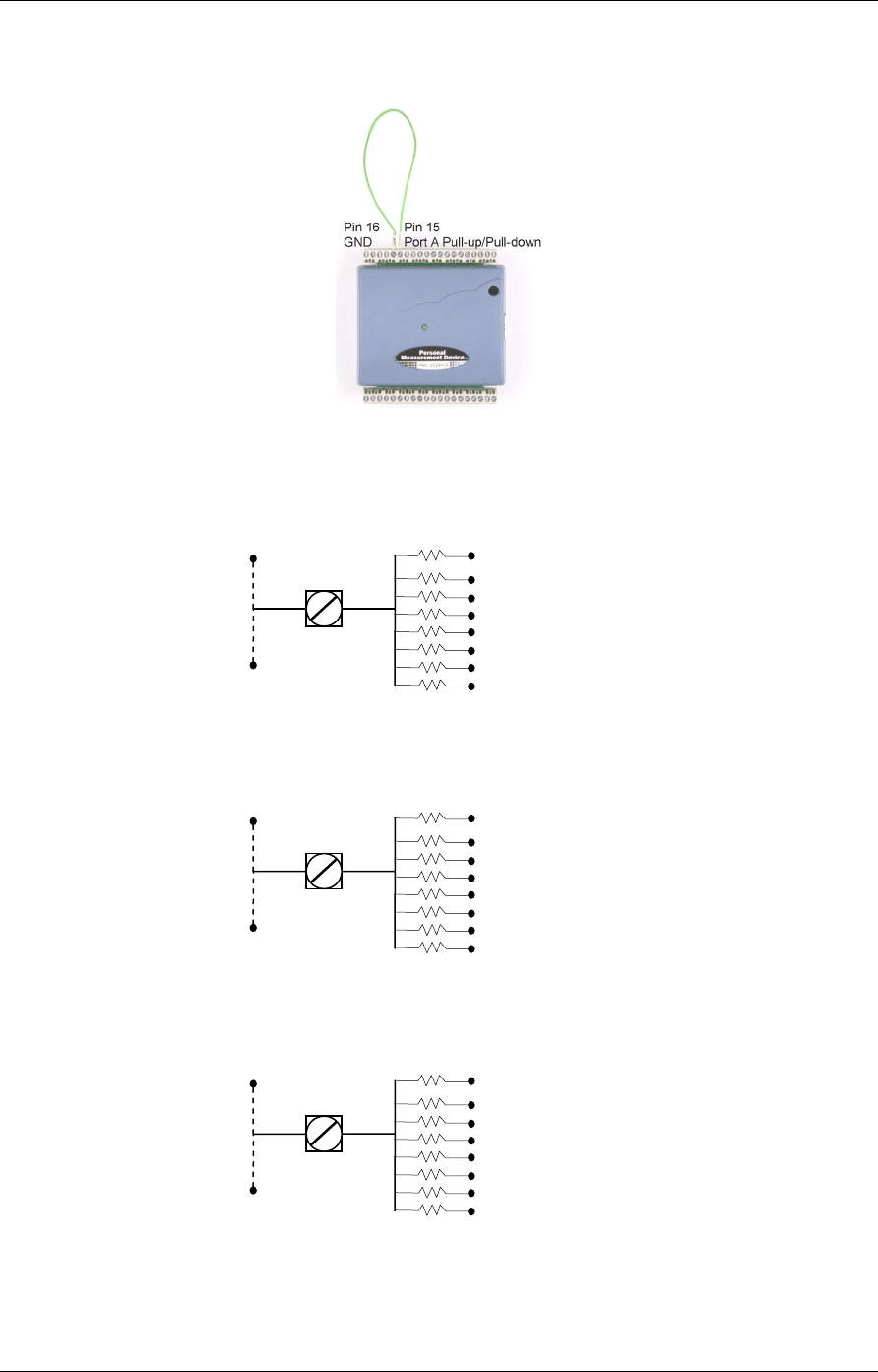
Figure 3-9. Schematic showing Port C pull-up/pull-down wiring options
USB +5 V
GND
DIO 7 (Port C7)
DIO 6 (Port C 6)
DIO 5 (Port C5)
DIO 4 (Port C4)
DIO 3 (Port C3)
DIO 2 (Port C2)
DIO 1 (Port C1)
DIO 0 (Port C0)
Port C
Pin 11
Pull-up
Pull-down
GND
DIO 7 (Port A7)
DIO 6 (Port A6)
DIO 5 (Port A5)
DIO 4 (Port A4)
DIO 3 (Port A3)
DIO 2 (Port A2)
DIO 1 (Port A1)
Pin 15
Pull-up
Port A
Pull-down
USB +5 V
DIO 0 (Port B0)
GND
DIO 7 (Port B7)
DIO 6 (Port B6)
DIO 5 (Port B5)
DIO 4 (Port B4)
DIO 3 (Port B3)
DIO 2 (Port B2)
DIO 1 (Port B1)
Pin 13
Pull-up
Port B
Pull-down
3-6