


PMD-1024HLS User's Guide Functional Details
20 CTR
19 GND
18 GND
17 GND
16 GND
15
14 USB +5 V
13
12 GND
11 Port C Pull-up / Pull-down
10 USB +5 V
9GND
8Port C7
Port A Pull-up / Pull-down
Port B Pull-up / Pull-down
7Port C6
6Port C5
5Port C4
4Port C3
3Port C2
2Port C1
1Port C0
GND 40
GND 31
USB +5 V 30
GND 29
Port A7 28
Port B7 39
Port B6 38
Port B5 37
Port B4 36
Port B3 35
Port B2 34
Port B1 33
Port B0 32
Port A6 27
Port A5 26
Port A4 25
Port A3 24
Port A2 23
Port A1 22
Port A0 21
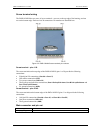
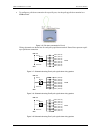
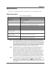
Digital I/O terminals (Port A0 to A7, Port B0 to B7, Port C0 to C7)
Connect up to 24 digital I/O lines to the screw terminal containing pins 1 to 8 (Port C0 to Port C7), pins
21 to 28 (Port A0 to Port A7), and pins 32 to 39, (Port B0 to Port B7). Refer to the pinout diagram on
page 3-2 for the location of these pins. You can configure each digital port for either input or output.
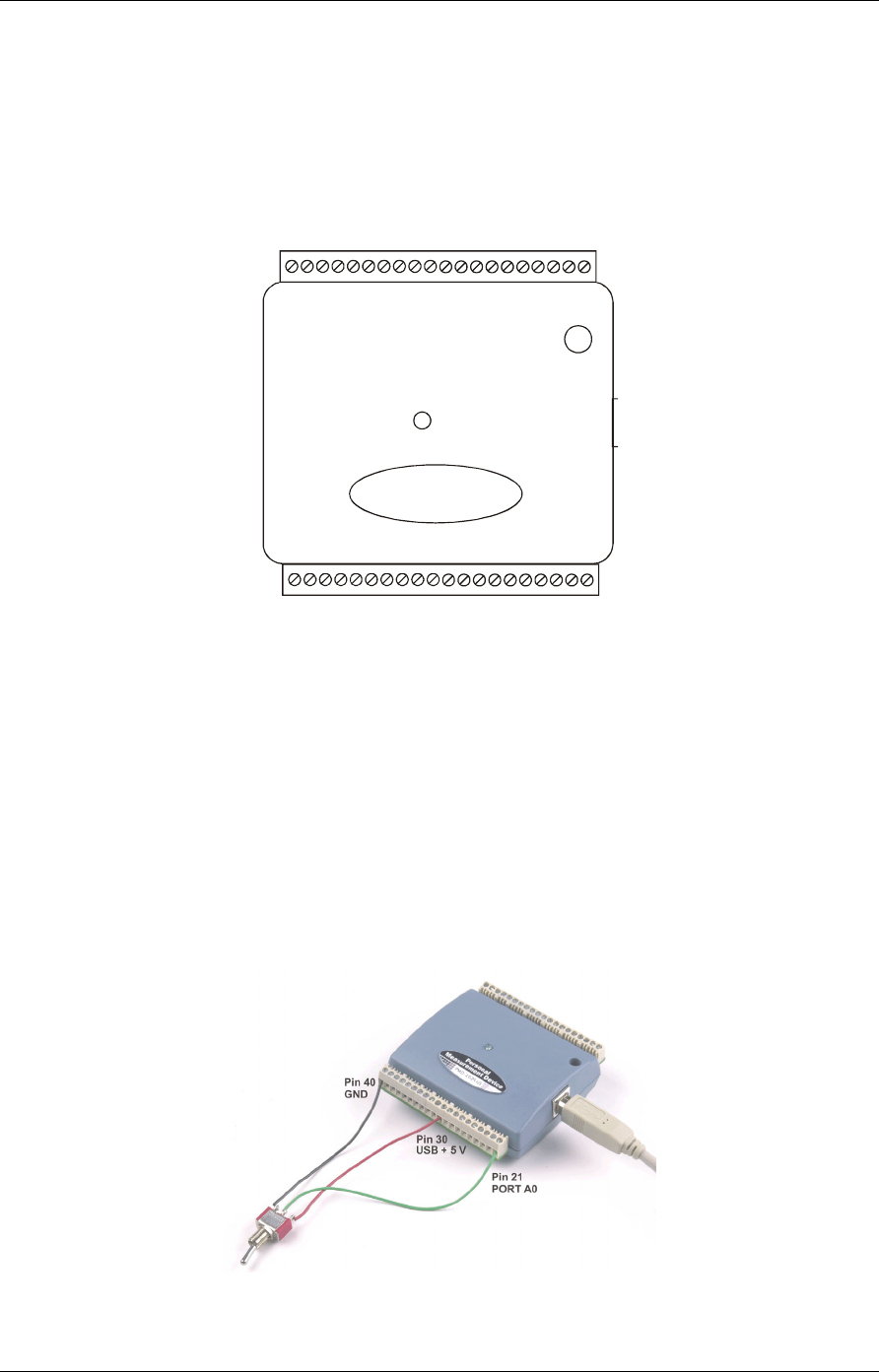
When configured for input, you can use the PMD-1024HLS digital I/O terminals to detect the state of any
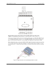
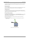
TTL level input. Refer to the switch shown in Figure and the schematic shown in . If you
set the switch to the +5 V input, Port A0 reads TRUE (1). If you move the switch to GND, Port A0 reads
FALSE.
3-3
Figure 3-3. Digital connection of Port A0 detecting the state of a switch
Figure 3-4
3-3