


PMD-1024HLS User's Guide Functional Details
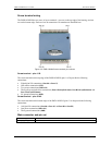
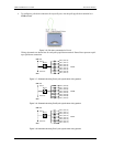
Screw terminal wiring
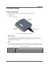
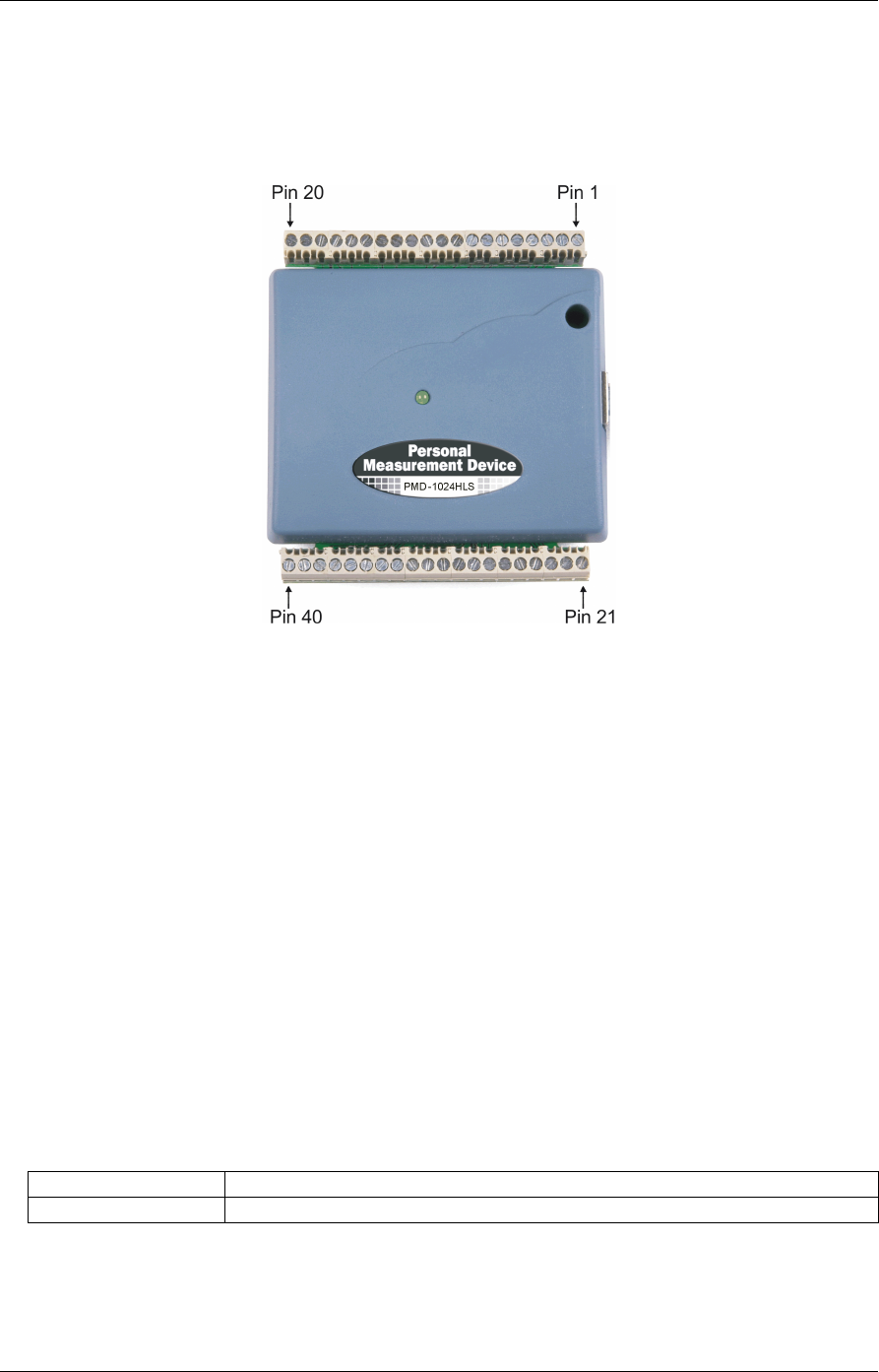
The PMD-1024HLS has two rows of screw terminals—one row on the top edge of the housing, and one
row on the bottom edge. Each row has 20 connections. Pin numbers are identified here.
Figure 3-2. PMD-1024HLS screw terminal pin numbers
Screw terminal – pins 1-20
The screw terminals on the top edge of the PMD-1024HLS (pins 1 to 20) provide the following
connections:
Eight digital I/O connections (
Port C0 to Port C7)
One counter connection (CTR)
Two power connections (USB +5 V)
Three pull-up and pull-down connections (
Port A Pull-up/Pull-down, Port B Pull-up/Pull-down and
Port C Pull-up/Pull-down)
Six ground connections (
GND)
Screw terminal – pins 21-40
The screw terminals on the bottom edge of the PMD-1024HLS (pins 21 to 40) provide the following
connections:
16 digital I/O connections (
Port A0 to Port A7, and Port B0 to Port B7)
One power connection (USB +5 V)
Three ground connections (
GND)
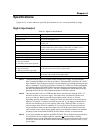
Main connector and pin out
Connector type Screw terminal
Wire gauge range 16 AWG to 30 AWG
3-2