


8
Fi
g
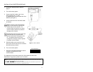
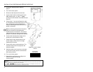
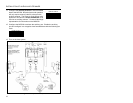
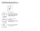
ure 4a: POS Di
p
Switch
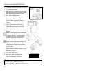
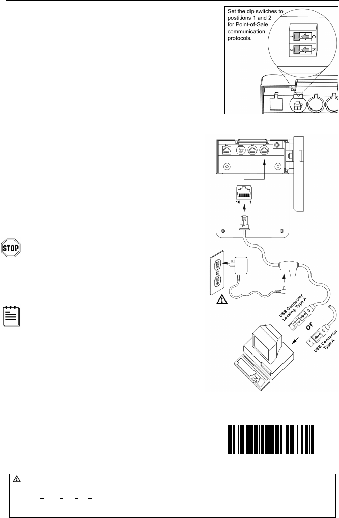
Fi
g
ure 4b: USB, Interface
INSTALLATION FOR USB INTERFACE
1. Follow the “Getting Started” steps on page 3.
2. Turn off the host system.
3. Determine if your application requires USB
Keyboard communication protocols or USB
Point-of-Sale communication protocols.
4. If you require USB Keyboard
communication protocols, skip to step 5.
If you require USB Point-of Sale
communication protocols set the dip
switches shown in figure 4a to positions
1 and 2.
5. Connect the PowerLink cable to the
10-pin USB interface jack. It is the 2
nd
round opening from the left side of the
MS7220 (see figure 4b).
6. Connect the other end of the USB cable to
the host.
Before continuing verify that the USB cable
is connected to the appropriate interface
jack on the scanner. An incorrect cable
connection can cause communication
problems or potential damage to the
scanner.
Plugging the scanner into the USB port of
the PC does not guarantee that scanned
information will appear at the PC. A
software driver and correct configuration
setting are also required for proper
communication.
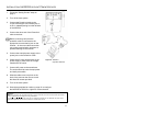
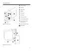
7. Slide the cable cover into place on the back
of the scanner then secure it with the three
M3 screws provided.
8. Turn on the host system.
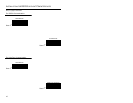
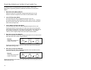
9. Scan the Enable USB Defaults bar
code to configure the MS7220 for
USB communication.
Caution:
To maintain compliance with applicable standards, all circuits connected to the scanner must meet the requirements
for SELV (Safety Extra Low Voltage) according to EN 60950.
To maintain compliance with standard CSA C22.2 No. 60950-00/UL 60950 and norm EN 60950, the power source
should meet applicable performance requirements for a limited power source.
³999978
Enable USB Defaults