3
SCALE PROGRAM MODE
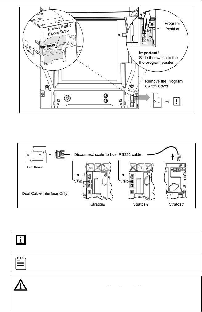
Figure 3. StratosS Calibration Seal and Switch Location
5. Disconnect the scale-to-host RS232 cable from the unit (dual cable
interface only.)
Figure 4. Disconnect scale-to-host RS232 Cable
6. Reinstall the platter and connect AC power to the scanner.
Check the AC input requirements of the power supply to make sure the voltage matches
the AC outlet. The outlet should be located near the equipment and be easily
accessible.
Metrologic recommends using a switched AC outlet. The switch should be located on
the operator’s side of the checkout counter in close proximity to the scanner/scale to
facilitate calibration and service of the unit.
To maintain compliance with applicable standards, all circuits connected to the scanner
must meet the requirements for SELV (Safety Extra Low Voltage) according to EN/IEC
60950-1.
To maintain compliance with standard CSA C22.2 No. 60950-1/UL 60950-1 and norm
EN/IEC 60950-1, the power source should meet applicable performance requirements
for a limited power source.


